

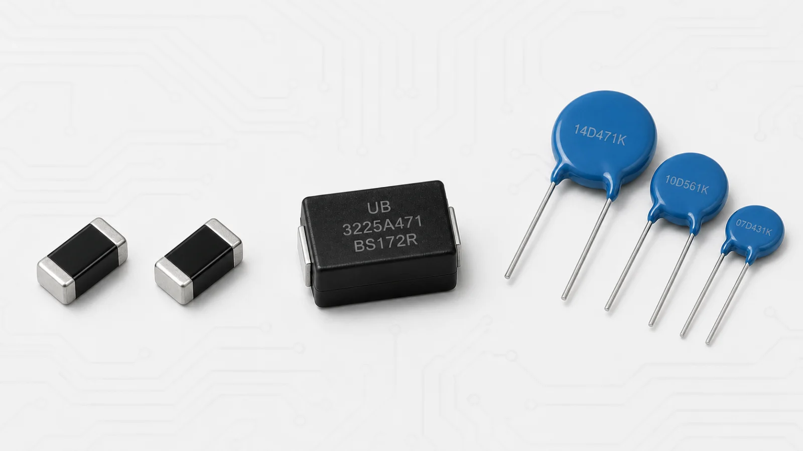
Surface-mount metal-oxide varistors (SMD MOVs; Chinese: 贴片金属氧化物压敏电阻) and through-hole metal-oxide varistors (TH MOVs; Chinese: 插件式金属氧化物压敏电阻) use the same basic voltage-dependent ceramic principle, but their construction and most suitable applications can be very different.
A small multilayer SMD varistor may protect an IC from ESD, while a 14 mm radial disc MOV may suppress a much higher-energy surge at an AC input. There are also molded SMD MOVs that bridge part of the gap. Therefore, “SMD or through-hole” is not only an assembly decision; it is also a transient-energy, voltage, capacitance, layout and safety decision.
Short answer: use an SMD MOV when compact automated assembly and local board-level protection are primary needs. Use a through-hole MOV when the design needs a conventional radial device with larger surge-energy options, flexible lead spacing and straightforward power-input placement. Always verify the actual ratings because exceptions exist.
Terminology Before Comparing
The terms can be confusing:
- SMD MOV: a broad category of surface-mount metal-oxide varistors.
- MLV — multilayer varistor: 多层片式压敏电阻, a common compact SMD MOV construction.
- Molded SMD MOV: a larger surface-mount device that may contain a monolithic or disc-like MOV element.
- Through-hole MOV: 插件式 or 直插式压敏电阻, normally with two radial leads.
- Disc MOV: 圆片式 or 碟片式压敏电阻, commonly referring to the radial through-hole form.
Because SMD MOV includes both small MLVs and larger molded products, no single statement about voltage or surge capability applies to every SMD device.
Quick Comparison Table
| Factor | SMD MOV | Through-hole MOV |
|---|---|---|
| Mounting | Surface mount, usually tape and reel | Radial leads inserted through PCB holes |
| Common constructions | Multilayer ceramic, molded monolithic or disc based | Coated metal-oxide ceramic disc |
| Typical use | Local PCB ESD/transient protection; selected power-input applications | Power-input, appliance and higher-energy surge protection |
| Board area | Usually compact with low profile | Larger body and keep-out area |
| Surge range | Very wide; small MLV to high-energy molded SMD | Wide range with many established disc sizes |
| Capacitance | Can be critical, especially for MLVs on signal lines | Usually less relevant on power lines but still specified |
| Assembly | Reflow and automated placement | Insertion plus wave, selective or manual soldering |
| Mechanical concern | PCB flex and solder-joint stress | Lead forming, vibration and body clearance |
| Thermal coordination | Depends on construction and PCB heat path | Easier to pair physically with some thermal disconnects |
Construction Differences
Multilayer SMD MOV
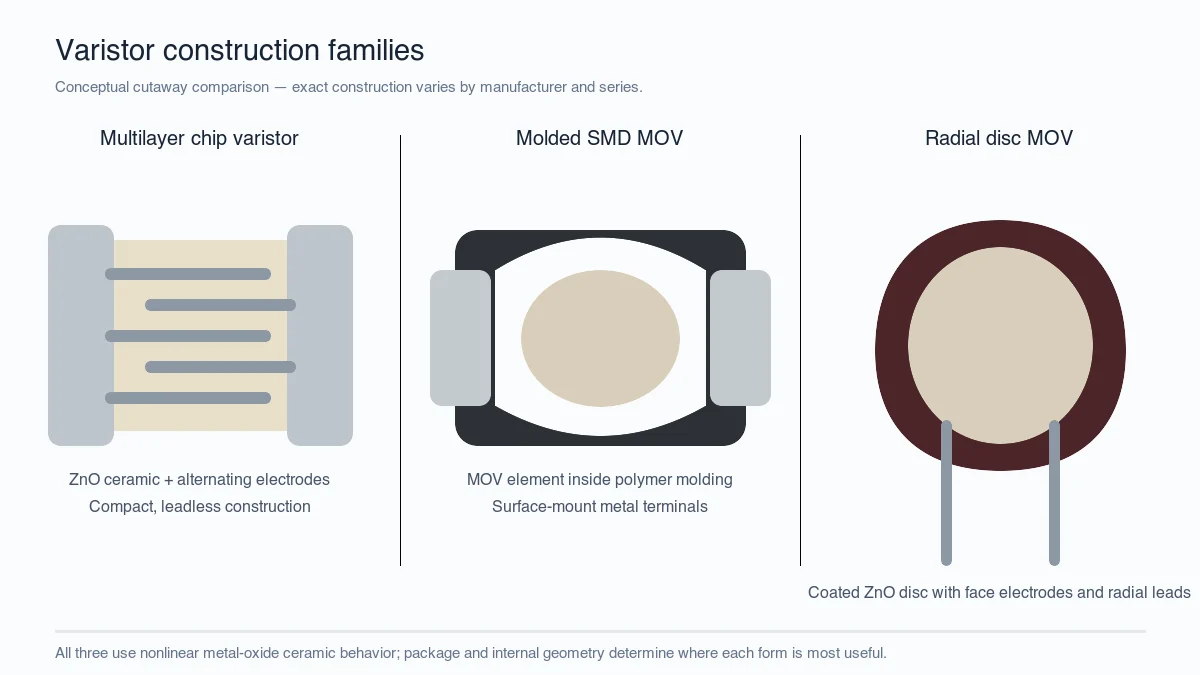
An MLV contains alternating semiconducting ceramic layers and internal electrodes. The overlap creates many active regions in a compact chip. This makes it suitable for low-profile automated assembly and local protection close to connectors or ICs.
Its electrical behavior depends on ceramic formulation, layer thickness, electrode overlap and package size. Small dimensions do not necessarily mean low clamping voltage, and identical case sizes can have different capacitance and pulse ratings.
Molded SMD MOV
A molded surface-mount MOV may use a larger monolithic or disc-like element with metal terminals inside a polymer body. This can provide power-input voltage and surge capability beyond many small MLVs while retaining reflow assembly.
Through-hole disc MOV
A radial MOV uses a sintered ceramic disc with electrodes on both faces, attached leads and an insulating coating. Disc diameter is visually related to active volume, and common families include approximately 5, 7, 10, 14, 20 and 25 mm sizes. The datasheet remains the authority for actual ratings.
Voltage Range and Circuit Position
Small MLVs are widely available for low-voltage board-level circuits. Larger MLVs and molded SMD MOVs extend into higher-voltage and higher-energy applications. Through-hole MOVs cover low-voltage DC through high-voltage AC families and are especially common across mains inputs.
The maximum continuous voltage must match the worst-case normal circuit voltage. Do not select from the nominal varistor-voltage code alone. For AC use, check the specified RMS rating; for DC use, check the DC rating.
Surge Current and Energy
Through-hole disc MOVs offer many established high-current and energy options because their active ceramic volume can be increased with disc size and thickness. A larger disc often provides more surge capability within the same product family.
Small MLVs are often optimized for ESD, EFT and lower-energy board-level transients. Some automotive or large-format MLVs have substantial surge ratings, and some molded SMD MOVs can handle power-line surge currents. Consequently, package type is only a screening factor.
Compare the same waveform and pulse count. An 8/20 μs peak-current rating, a 10/1000 μs energy value and an IEC 61000-4-2 ESD claim describe different tests.
Clamping Performance
Clamping voltage depends on current. A comparison is valid only when both devices are evaluated at relevant and comparable test currents. A small MLV measured at a few amperes should not be judged directly against a disc MOV measured at tens of amperes.
PCB and lead inductance add overshoot. SMD placement can minimize loop area and improve very-fast transient behavior. A through-hole MOV may carry more energy but its longer leads can add inductance unless they are kept short.
Capacitance and Signal Integrity
For power lines, MOV capacitance is often secondary. For data, sensor and analog lines, it may be a decisive parameter. Some MLVs have relatively high capacitance, while dedicated low-capacitance chip protectors are designed for signal interfaces.
Through-hole disc MOVs are rarely the first choice for high-speed data lines because of size, lead inductance and capacitance. A TVS diode or specialized low-capacitance suppressor may be more appropriate.
PCB Space, Assembly and Manufacturing
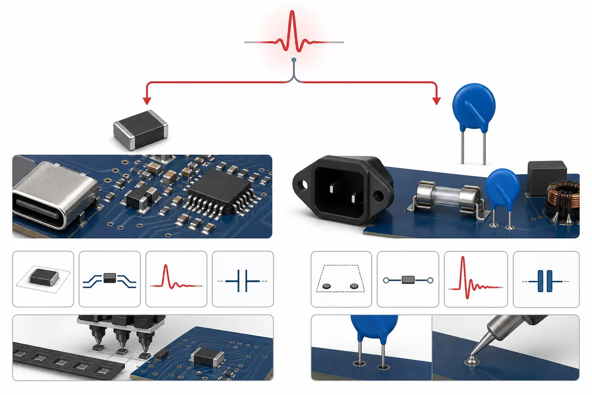
SMD MOVs support tape-and-reel supply, pick-and-place and reflow. They reduce lead-forming operations and can be positioned close to the protected node. The design must control pad geometry, reflow stress and board bending.
Through-hole MOVs require insertion and a through-hole soldering process but offer flexible lead spacing and body stand-off. They can be convenient when the product already contains other through-hole power components or when physical spacing and thermal isolation are important.
Assembly cost depends on the entire production line. An SMD part is not automatically cheaper if it requires a special high-thermal-mass reflow profile, and a through-hole part may be efficient in a mixed power assembly using selective soldering.
Reliability and Safety Coordination
Both forms can degrade after excessive pulse or continuous-voltage stress. Failure may appear as leakage increase, varistor-voltage shift, cracking, short circuit or open circuit.
For AC power applications, consider fusing and thermal disconnection. Through-hole thermally protected MOVs are widely available, including versions with a monitoring lead. Surface-mount solutions also exist, but their fault behavior and heat path must be reviewed as a complete assembly.
Safety approvals, AEC-Q200 qualification, flammability and environmental compliance are series-specific. Package type alone carries no certification.
Which Type Fits Common Applications?
| Application | Typical starting point | Why |
|---|---|---|
| ESD at a button or connector | Low-capacitance MLV or other SMD suppressor | Small, short layout and local protection |
| Microcontroller supply rail | MLV, subject to capacitance and voltage | Compact board-level transient suppression |
| AC appliance input | Through-hole disc MOV or rated molded SMD MOV | Higher-energy and mains-voltage options |
| LED driver mains input | Through-hole MOV is a common starting point | Established power-input surge ratings |
| Compact automated power module | Molded high-energy SMD MOV | Reflow assembly with power-surge capability |
| Automotive ECU low-voltage rail | Automotive-qualified MLV or other rated suppressor | Local protection; qualification and pulse matching required |
| High-speed communication line | Specialized low-capacitance suppressor | Signal integrity is critical |
Practical Selection Flow
- Define normal voltage: AC RMS or DC, including tolerance and abnormal expected states.
- Define the transient: ESD, EFT, surge, switching event or automotive pulse.
- Estimate required current and energy: use the actual waveform and source impedance.
- Set the allowable residual voltage: based on downstream absolute maximum ratings.
- Check capacitance and leakage: especially for signal and low-power circuits.
- Choose the construction: MLV, molded SMD or radial disc.
- Check mechanical and production constraints: footprint, height, reflow, insertion and board flex.
- Check reliability evidence: pulse life, temperature derating, qualification and safety coordination.
- Test the assembled product: component ratings do not replace system verification.
Common Comparison Mistakes
- Assuming every SMD MOV is an MLV
- Assuming every through-hole MOV is for AC mains
- Comparing only nominal varistor voltage
- Comparing clamping values at different current levels
- Treating disc diameter or chip size as a complete rating
- Ignoring capacitance on signal lines
- Ignoring fuse and thermal coordination on power lines
- Replacing one form with another without checking assembly and safety spacing
Frequently Asked Questions
Is an SMD MOV faster than a through-hole MOV?
Both metal-oxide devices respond rapidly at the material level. In a real circuit, the shorter loop of an SMD device can reduce inductive overshoot. “Response time” alone does not determine protection quality.
Can an SMD MOV replace a 14D disc MOV?
Only if a specific SMD device matches continuous voltage, clamping curve, peak current, energy, pulse life, temperature, safety and assembly requirements. A small MLV is generally not a direct replacement for a power-input disc MOV.
Which type lasts longer?
Lifetime depends on voltage margin, pulse amplitude, pulse count, temperature and construction. Neither mounting style is inherently longer-lived in every application.
Which type is better for automotive electronics?
It depends on the protected node and required pulse. Automotive-qualified MLVs are common near electronics, while other MOV forms may be used on higher-energy power paths. Confirm AEC-Q200 and the relevant vehicle pulse requirements separately.
Conclusion
SMD MOVs provide compact automated assembly and can be placed close to sensitive circuitry. Through-hole MOVs provide a familiar radial form with broad power-input and surge-energy options. Between them are molded high-energy SMD devices that combine surface mounting with larger active elements.
The correct choice is determined by the normal voltage, transient waveform, allowable clamping voltage, pulse endurance, capacitance, layout, assembly and safety strategy—not by mounting style alone. For the shared MOV terminology, see What Is a Varistor? MOV Basics and Key Parameters.












