

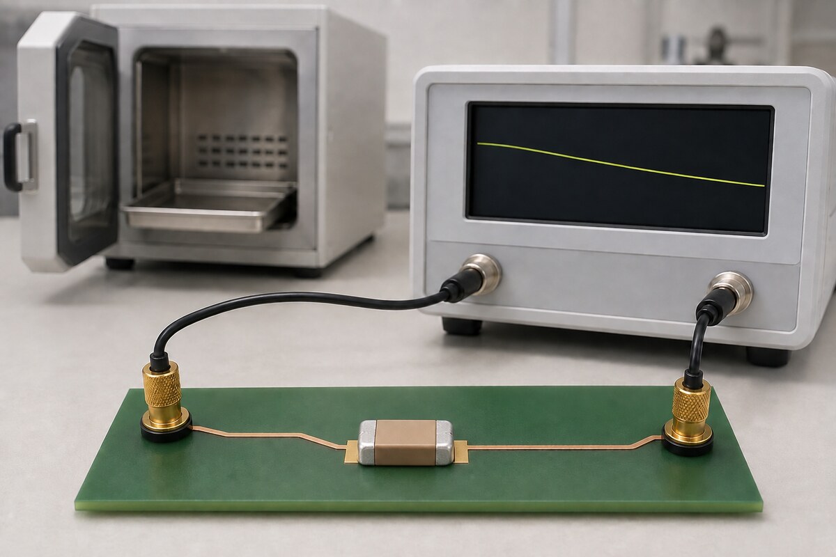
An MLCC that measures higher after reflow has not gained permanent capacitance. For a high-permittivity ferroelectric dielectric, a heat history that crosses the relevant Curie point may reverse the prior capacitance-aging state and reset its clock. After cooling below that point, logarithmic aging restarts. The new reading reflects a possible reset clock, not a better reliability grade.
Identify the dielectric, last heat, referee time, measurement time, temperature, frequency, AC test level, and any DC voltage. The electronic-components overview gives broader context, while the datasheet abbreviations guide decodes labels. Neither replaces the exact part specification.
Reflow changes the aging clock, not the capacitor’s reliability grade
Murata explains that capacitance lost through aging in its high-dielectric-constant ceramic capacitors can recover when the part is heated above the page’s approximate 125 °C Curie temperature. Aging starts again after the capacitor cools below that point (A1). This mechanism can explain a higher bench reading after soldering without implying a permanent increase in rated capacitance.
A KYOCERA AVX paper says its illustrated process can be reversed above 120 °C (A4). This is not a universal threshold. Dielectric and actual temperature-time history determine whether reflow crosses the relevant Curie point. Recovery alone proves nothing about cracking, insulation resistance, failure rate, or service life.
Start with dielectric behavior, not the word ceramic
Murata describes temperature-compensating capacitors as not having this aging characteristic and names X5R/X7R high-dielectric-constant examples (A1), while Knowles AN0006 calls Class I C0G aging negligible and discusses X7R, Y5V, and Z5U (A3). High-K ferroelectric materials need a time-history check; the dielectric code and source scope matter.
Class numbers are not enough. KEMET F3101 labels X7R Class II and Z5U Class III, while Knowles and AVX use broader Class 2/Class II wording. Retain dielectric code, manufacturer, series, and source version instead of forcing one taxonomy.
Percent per decade describes logarithmic time
Knowles defines k as percentage capacitance loss for a tenfold increase in age. After the poorly defined first hour, AN0006 uses C(t) = C1 × [1 − (k/100) × log10(t)]. Here C1 is capacitance at one hour and t is hours from aging start. Thus 1–10, 10–100, and 100–1,000 hours are successive logarithmic decades.
In the Knowles/Syfer X7R typical example, “1% per decade” is not 1% every ten hours, 1% per year, or compounding from each prior value. In that equation, each decade adds the same k-percentage decrement referenced to C1. Use only the applicable manufacturer’s rate and convention; never extrapolate to time zero or turn a typical example into a limit.
Three clocks determine whether two readings are comparable
Many discrepancies are timing discrepancies. Calendar age may not identify the last above-Curie event, so record three clocks before comparing receiving, post-reflow, and laboratory values.
| Clock | Question it answers | Evidence to retain | Invalid shortcut |
|---|---|---|---|
| Last heat / last Curie excursion | When did this aging cycle begin? | Process, actual component temperature, duration, and cooling completion | Substituting ship date, receipt date, or oven setpoint |
| Referee time | At what reference age is capacitance and tolerance indexed? | Full order code, document revision, rate identity, and permitted correction | Assuming every MLCC uses 1,000 hours or that measurement is forbidden earlier |
| Measurement time | How long after aging start was this reading taken? | Timestamp, temperature, frequency, AC level, DC condition, instrument, and fixture | Comparing unlike times or borrowing another part’s correction rate |
The reviewed KEMET C1023 X7R family indexes measurements to either 48 or 1,000 hours and directs users to the part-number-specific sheet (A2). These are product-document rules, not industry constants. A measurement at another age can be useful, but a specification verdict requires the applicable correction method and test conditions.
A de-aging bake is not a universal reflow recipe
Procedures differ. Knowles recommends 160 °C for 1.5 hours, then 24 hours at 20 °C ±2 °C before measurement. Legacy KEMET F3101 instead gives 150 °C for half an hour or 125 °C for two hours, with measurement usually delayed at least 10 hours (A5).
These schedules are not interchangeable best practices. Reflow assembles a board; controlled de-aging preconditions a measurement. Never heat production hardware for a larger reading unless the exact specification and all component, board, and assembly limits permit it.
Why one X7R aging number cannot become a default
The source set contains three legitimate but non-equivalent X7R values. Knowles lists 1% per decade as a typical Syfer X7R value. The legacy F3101 application note lists 2.0% typical for its X7R discussion. The current KEMET C1023 X7R family lists 3.0% maximum capacitance loss per decade hour. Manufacturer, era, product family, formulation, and statistical qualifier all changed.
Z5U examples reinforce the warning: F3101 lists 5.0% typical, while AN0006 gives 6% for another manufacturer’s material. The figures prove only that exact-part data is necessary. Do not average, rank, transfer, or infer a missing rate from a neighboring graph.
Keep aging outside the DC-bias and temperature arithmetic
KYOCERA AVX treats temperature, applied DC bias, and aging in separate sections. The KEMET C1023 product document likewise places temperature coefficient and aging rate in different specification rows with different references. Knowles notes that DC bias can move the apparent point on an aging curve, which indicates interaction—not identity.
Do not publish aging loss + DC-bias loss + temperature loss = total loss. Obtain same-part data at the intended temperature, DC voltage, frequency, AC level, and time after last heat. Combine effects only through a manufacturer model or validated common reference. Aging is a thermal-history question; biased effective capacitance is a separate work-point analysis.
A reproducible troubleshooting and verification workflow
This workflow is suitable for incoming inspection, a reflow comparison, or a customer-return investigation. It produces one of three defensible outcomes: specification-comparable, missing conditions, or controlled retest required. It does not invent a pass result before the measurements exist.
- Lock the object. Record manufacturer, full orderable part number, lot, dielectric, nominal capacitance, tolerance, rated voltage, case size, and datasheet revision.
- Find the controlling fields. Capture aging rate, typical/maximum/limit identity, referee time, tolerance definition, and the manufacturer’s permitted time correction. Mark a missing field unknown.
- Reconstruct thermal history. Identify the last process that could cross the relevant Curie point, with evidence of actual component temperature, duration, and cooling completion—not only the oven setting.
- Define the question. Separate specification acceptance, process trending, reflow-effect diagnosis, and powered-circuit capacitance. One reading cannot answer all four.
- Reproduce test conditions. Set temperature, LCR frequency, AC test level, ALC or source impedance, fixture, and DC condition exactly as the controlling document requires; perform open/short compensation.
- Record real time. Save measurement timestamp, time after last heat, raw value, sample count, instrument, and fixture for every unit. Do not pool samples measured after different waits.
- Align to the referee age. If the reading is taken elsewhere, normalize only with the applicable part/manufacturer rate and method. Never borrow the Knowles or legacy F3101 schedule for an unrelated part.
- Investigate residual differences. After time alignment, check temperature, DC bias, AC amplitude, frequency, contact, fixture, cracking, and other damage as separate causes.
- Issue the verdict. Report pass or fail only when object, thermal history, time, method, and limits are complete. Otherwise list the missing evidence and label the result pending verification.
If a controlled de-aging comparison is genuinely required, use a procedure authorized for the exact product and keep treated and untreated groups separate. A single observation that “capacitance came back” confirms neither long-term margin nor assembly reliability.
Frequently asked questions
Why does MLCC capacitance increase after reflow?
A high-K ferroelectric dielectric may de-age when its actual temperature crosses the relevant Curie point. After cooling, a new aging cycle begins, so an early reading can exceed the pre-reflow value. The amount of recovery depends on material and real thermal history; the oven peak alone cannot guarantee a complete reset.
Is a measurement before referee time automatically out of specification?
No. Referee time is the reference age at which the manufacturer indexes capacitance and tolerance. An earlier or later measurement can support a verdict only when the exact part provides an applicable aging rate, correction method, and complete measurement conditions.
Does C0G need the same aging correction as X7R?
The reviewed Murata and Knowles sources describe this Class I C0G aging as absent or negligible, so a high-K correction should not be copied to C0G. The exact C0G part still has specified tolerance, temperature, frequency, and test-level conditions that must be followed.
Can every MLCC be baked at 160 °C for 1.5 hours?
No. That is a Knowles/Syfer recommendation within AN0006, not an industry procedure. Other manufacturer documents use different temperature-time pairs. Any treatment must be authorized for the full part and remain compatible with terminations, board materials, and the assembled product.
How can I separate aging loss from DC-bias loss?
First determine whether DC voltage was present during the reading, then align temperature, frequency, AC test level, last heat, and measurement time. Aging follows elapsed time after thermal reset; DC bias describes an energized operating point. Both may coexist, but each needs its own evidence.
Decision rule and first-party references
Treat post-reflow recovery as a thermal-history clue. Identify the dielectric, interpret percent per decade on a logarithmic clock, and keep last heat, referee time, and measurement time separate. Bind every rate and bake schedule to its manufacturer document, and never convert capacitance recovery into a reliability claim.











