

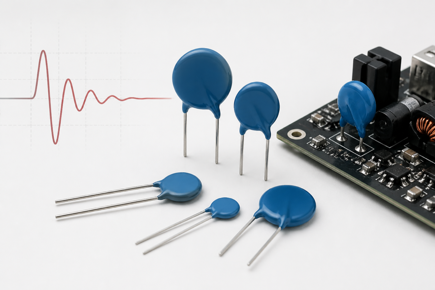
A varistor is a voltage-dependent resistor used to limit transient overvoltage. Under normal operating conditions, it presents a high resistance and draws very little current. When the voltage rises above its characteristic threshold, its resistance falls rapidly, creating a temporary path for surge current and helping to limit the voltage seen by the protected circuit.
The term varistor describes the device function. MOV means metal-oxide varistor, the most common varistor technology used for power-line and general surge protection. This article explains how an MOV works, the main datasheet parameters, and the checks required before selecting one.
What Is a Metal-Oxide Varistor?
An MOV is a nonlinear, bidirectional voltage-clamping component. Its active material is usually based on zinc oxide with other metal-oxide additives. The many grain boundaries inside the ceramic create a nonlinear voltage-current characteristic.
Because the characteristic is approximately symmetrical, an MOV can clamp positive and negative transients. It is normally connected in parallel with the circuit or load that needs protection.
- At normal voltage: the MOV remains in a high-resistance state.
- During an overvoltage transient: its resistance decreases sharply and surge current is diverted through the MOV.
- After the transient: it returns to a high-resistance state, provided the event has not exceeded the device limits.
An MOV does not remove a surge or hold the voltage at an exact fixed value. Its purpose is to reduce the transient to a lower clamping level. The actual voltage depends on surge current, waveform, component tolerance, temperature, wiring inductance, and the selected MOV.
How an MOV Protects a Circuit
In a typical power-line application, the MOV is placed across line-to-line or line-to-neutral. When a switching transient, induced lightning surge, or another short-duration overvoltage appears, the MOV conducts and absorbs part of the pulse energy. The remaining voltage across the circuit is the clamping voltage under that specific test condition.
Placement matters. Long PCB traces or wires add inductance and can increase the voltage seen by the protected load. For effective protection, the connection between the MOV, surge path, and protected circuit should be short and appropriately sized.
Key MOV Datasheet Parameters
MOV parameters must always be read together with their test conditions. Similar-looking values are not interchangeable.
1. Maximum Continuous Operating Voltage
The maximum continuous operating voltage is the highest AC RMS or DC voltage that may be applied continuously under the stated conditions. Datasheets commonly provide separate VAC and VDC ratings.
This is the first selection check. The rating must remain above the highest actual system voltage, including normal line tolerance and expected steady-state variation. It should not be selected only from the nominal voltage printed on the equipment.
2. Varistor Voltage
Varistor voltage is a reference value measured at a specified DC test current, often 1 mA for many radial MOV families. It may therefore be shown as V1mA. The allowable tolerance is stated in the datasheet.
Varistor voltage is not the same as maximum continuous voltage, and it is not the same as the clamping voltage during a surge.
3. Clamping Voltage
Clamping voltage is the voltage measured across the MOV while a specified pulse current flows through it. A value is meaningful only when the test current and waveform are also known.
When checking protection margin, compare the worst-case clamping voltage with the maximum voltage that the downstream circuit can tolerate. Also allow for component tolerance, surge-current variation, and layout-related overshoot.
4. Peak Surge Current
The peak surge-current rating describes the maximum pulse current for a defined waveform and number of applications. MOV datasheets often use an 8/20 μs current waveform, but the exact test must be confirmed.
A single-pulse rating does not mean the MOV can repeatedly withstand that current. Repetitive-pulse capability is lower and depends on pulse shape, interval, temperature, and cumulative degradation.
5. Energy Rating
Energy capability is usually expressed in joules for a specified pulse waveform. It indicates how much pulse energy the MOV can absorb under defined test conditions.
Do not compare energy values from different waveforms as if they were equivalent. The expected transient energy, source impedance, pulse duration, and repetition rate must be considered together.
6. Capacitance
An MOV has inherent capacitance. This is often acceptable on AC power lines, but it can affect high-frequency, communication, or sensitive signal circuits. In those applications, capacitance and signal integrity need separate review.
7. Leakage Current and Power Dissipation
Below the varistor-voltage region, a small leakage current still flows. Leakage can increase with temperature, aging, or damage. Datasheet limits for leakage, rated power, and operating temperature should be included in the design review.
How to Select an MOV
- Confirm the real operating voltage. Record nominal voltage, maximum tolerance, AC or DC operation, frequency, and abnormal steady-state conditions.
- Define the transient. Identify the source, peak voltage, available current, source impedance, waveform, energy, repetition rate, and applicable surge standard.
- Check the protection level. Verify that worst-case clamping voltage remains below the protected circuit’s withstand limit.
- Check pulse and lifetime capability. Review surge-current, energy, repetition, temperature, and derating rather than relying on a single headline rating.
- Review package and safety requirements. Consider mounting method, clearance, thermal protection, fusing, approvals, failure mode, and end-equipment standard.
Final selection should be verified using the manufacturer’s current datasheet and, where appropriate, testing in the actual circuit. MOV choice is a system-level decision rather than a simple voltage-code match.
MOV, MLV, TVS Diode, and GDT: What Is the Difference?
- Radial or disc MOV: commonly used for surge suppression on AC or DC power lines, with product families covering different voltage, current, and energy levels.
- MLV: a multilayer ceramic varistor typically used in compact surface-mount applications. Its construction and application range differ from a conventional disc MOV. See the MLV section.
- TVS diode: a semiconductor clamping device often selected when tighter voltage control or lower-voltage protection is required. Polarity, capacitance, pulse waveform, and power rating must be reviewed.
- GDT: a gas discharge tube suited to high surge currents, but with different response and follow-current behavior. It is often coordinated with another protection stage.
These devices are not automatic substitutes for one another. In many designs, coordinated protection uses more than one technology to balance surge capacity, clamping level, response, leakage, and capacitance.
Common MOV Applications
- AC mains input protection
- Power supplies and adapters
- Industrial controls and motor-related equipment
- Household appliances
- LED drivers and lighting power supplies
- Renewable-energy and charging equipment
- Relay, coil, and switching-transient suppression
The correct MOV depends on its exact circuit position and surge environment. For example, protection at an AC input is different from protection of a low-voltage signal interface.
Aging, Failure, and Thermal Protection
MOVs can degrade after repeated or excessive transients. Degradation may increase leakage current and heating. A sustained abnormal overvoltage can also force an MOV into continuous conduction, creating a thermal risk.
Designs may therefore require an upstream fuse, thermal cutoff, thermally protected MOV, or another disconnect method. The choice depends on the power source, fault condition, applicable safety standard, and the MOV manufacturer’s instructions. An MOV should not be treated as an unlimited or maintenance-free surge absorber.
Frequently Asked Questions
Is every varistor an MOV?
No. A varistor is a broader functional category. MOV refers specifically to metal-oxide varistor technology, although MOVs are the most familiar varistors in circuit-protection applications.
Is varistor voltage the same as clamping voltage?
No. Varistor voltage is measured at a specified low DC test current, while clamping voltage is measured during a specified surge-current pulse. Their test conditions and design meanings are different.
Can a larger disc always replace a smaller MOV?
Not automatically. A larger disc may offer greater pulse capability within a product family, but voltage ratings, clamping behavior, tolerance, capacitance, package spacing, approvals, and circuit conditions must all be checked.
Should an MOV be connected in series or parallel?
For overvoltage clamping, an MOV is normally connected in parallel with the protected line or load. The complete protection circuit may also include series impedance, a fuse, or other coordinated components.
Reference Sources
- Littelfuse — The ABCs of MOVs
- Littelfuse — Selecting a Littelfuse Varistor
- TDK Electronics — Multilayer Varistors
This article provides general technical information. Always verify final component selection against the current manufacturer datasheet, circuit conditions, and applicable safety or EMC requirements.












