APPLICATION ENGINEERING

Circuit Protection Application Guides

Start with the interface, power rail or load you need to protect. Each path connects the electrical stress, component trade-offs, PCB placement and final-system validation.

Industrial Control

Industrial Interfaces and Inductive Loads

PLC I/O / RS-485 evidence boundary / industrial Ethernet / relays and solenoids

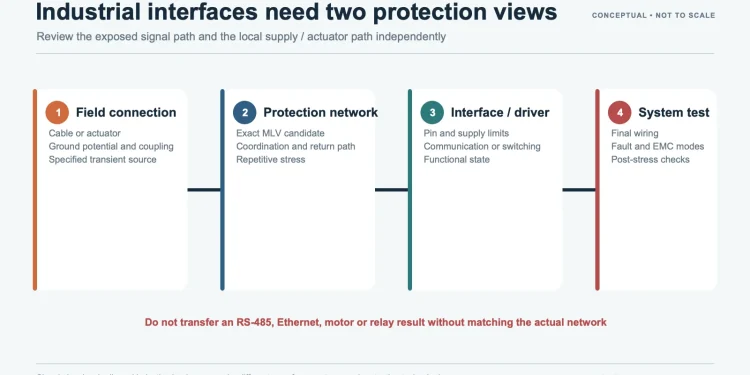
Account for field wiring, grounding, repeated disturbances and the required functional state after each test. ESD, EFT, surge and inductive switching events need separate source models, placement decisions and acceptance criteria.

Explore guides
Industrial interface protection workflow from field connection to final-system validation
Communications

Communication Interfaces and Long-Line Nodes

Ethernet / long copper links / audio / antenna and RF-adjacent interfaces

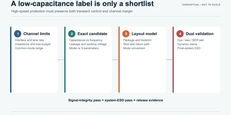
Evaluate capacitance, clamping, isolation, shielding and return paths without losing sight of the installed system. Cable length, outdoor routing and nearby conductive structures can change the surge path and the stress seen by each protection stage.

Explore guides
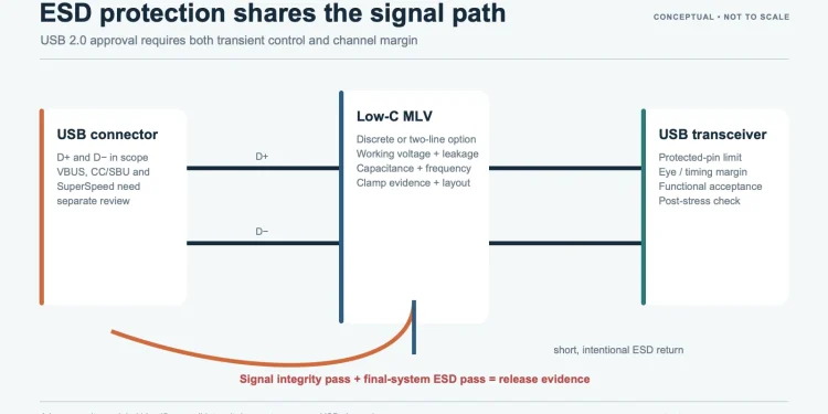
Communication interface protection workflow covering channel limits and final validation
LED Lighting

LED Driver Outputs and Module Interfaces

AC input / driver output / LED module / dimming and control interfaces

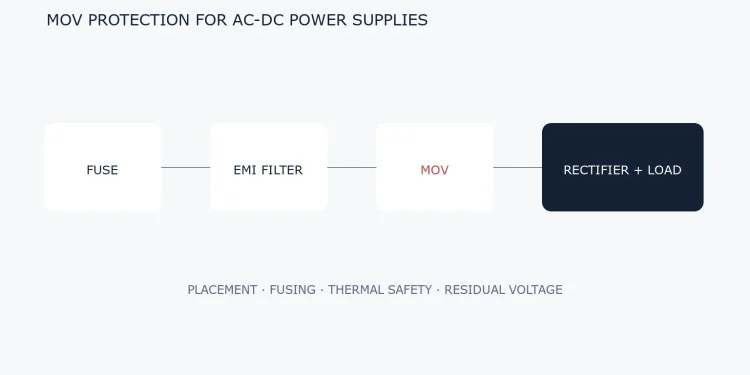
Identify mains surges, cable-coupled events, hot-plug stress and driver overshoot at the correct node. Treat AC-input safety and local DC protection separately, then verify the complete driver, connector, module and enclosure configuration.

Explore guides
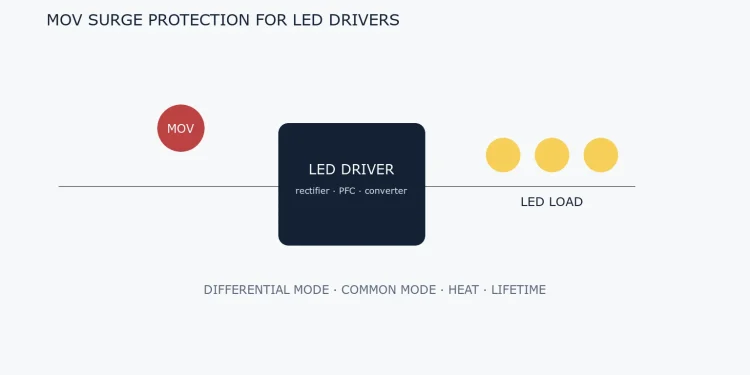
LED driver protection architecture from AC input through driver stage to LED load
MORE APPLICATIONS

Additional Application Paths

ENGINEERING WORKFLOW

Move from a Use Case to a Verifiable Design

  1. 01Define the nodeRecord the port, normal voltage, grounding, cable, installation and acceptable functional outcome.
  2. 02Identify the stressSeparate ESD, EFT, surge, automotive pulses, load dump and sustained faults.
  3. 03Match the deviceCheck the exact series and part number, waveform, current, temperature, capacitance, leakage and failure mode.
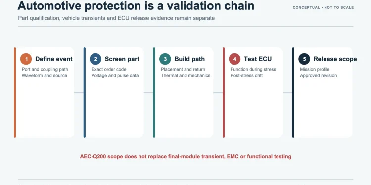
  4. 04Validate the systemConfirm function and post-stress condition on the final schematic, PCB, prototype and specified test setup.

A generator setting, the voltage at the equipment port and the current through a protection component are not the same quantity. Include the coupling network, source impedance, cable, filters, grounding and parallel paths when calculating or measuring the actual peak, energy, rise time, duration, polarity, interval and repetition count.

Check leakage, power loss, capacitance, insertion loss, temperature and signal integrity in normal operation; dynamic clamping, stage sharing and equipment function during a transient; and sustained overvoltage, short-circuit, open-circuit, thermal runaway and upstream coordination under abnormal conditions.

PROJECT INPUT

Have a Specific Circuit or Part Number?

Share the working voltage, interface or load, package limits, transient standard or waveform, and the validation stage. UBAEC can help organize the selection questions and evidence to check.

Submit an application question
Primary standards and technical references