

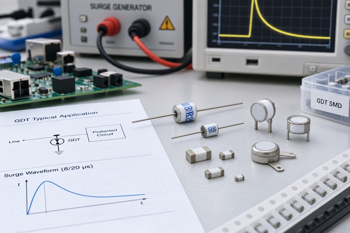
A gas discharge tube (GDT) can finish diverting the specified surge and still remain conductive. Once the tube has fired and entered its low-voltage arc state, the energized line may supply a second current after the transient source has decayed. That source-fed current is follow current. Whether it stops is a circuit question, not a conclusion that can be read from the GDT’s peak impulse-current number alone.
The design question begins after the generator pulse
An impulse discharge rating belongs to a defined waveform, peak, polarity, operation count, and interval. An 8/20 µs test and a 10/350 µs test are not interchangeable because their peaks match. Neither defines what a mains source, battery, or DC-link capacitor can deliver after the impulse.
Follow current has a different source. The surge initiates conduction, but the normal power system sustains it. Its magnitude is set by service voltage, source impedance, stored energy, current limiting, wiring, and the GDT’s conducting voltage. Two products using the same GDT can therefore produce different follow-current and extinction results.
Track the GDT through its operating states
Before sparkover, the tube is a high-impedance component. Ionization then develops through a glow region and, with sufficient current, into a low-voltage arc. In arc mode the GDT acts more like a crowbar than a precision clamp. DC and impulse sparkover voltage describe entry into conduction under stated slopes; arc voltage describes the on-state under a stated current. Neither proves that the tube will reset.
The current Bourns 2026 Series three-pole datasheet lists about 70 V glow voltage at 10 mA, about 10 V arc voltage at 1 A, and a glow-to-arc transition below 0.5 A. It separately rates 8/20 µs, 10/350 µs, 10/1000 µs, and AC duties. These are series-specific values, not universal GDT constants.
Extinction depends on the source and the reset condition
The arc collapses when the circuit can no longer sustain the discharge and the gas can deionize. Service voltage, available current, source impedance, frequency, DC polarity, recovery voltage, prior impulse energy, and temperature all matter. Observe beyond the surge tail.
An AC zero crossing often helps, but recovery voltage may re-establish the discharge and a low-impedance source may impose excessive current first. Test the unfavorable surge phase and capture several later cycles for delayed extinction or restrike.
DC has no periodic current zero. TDK’s note for LN8 stacked arresters uses arc voltage above DC operating voltage to obtain extinction. More arc chambers raise arc voltage but also impulse breakdown. This is an LN8-specific tradeoff, not permission to series-connect unspecified GDTs and assume safe reset.
Holdover voltage is a reset specification, not an operating limit
DC holdover voltage describes post-ignition behavior under a defined test network and time criterion. DC sparkover voltage asks when a high-impedance tube initiates discharge during a voltage ramp. Holdover asks whether an already conducting tube ceases discharge. They run in opposite parts of the event and must not be relabeled as equivalent ratings.
Read inequality signs, network, current, duration, and notes. The Bourns 2026 Series ties holdover to a network and a less-than-150 ms criterion. ITU-T K.12 selects one or more holdover tests by intended use. Its general two-electrode method uses a 100 A, 10/1000 µs impulse with defined 52 V, 80 V, or 135 V DC networks and requires turn-off below 150 ms; nominal DC sparkover of 230 V or above uses its Annex A circuit. K.12 excludes GDTs connected to power systems, so these are conditioned telecom tests, not universal operating limits.
Build separate AC and DC worst cases
For AC, document maximum RMS voltage, frequency, earthing, prospective fault current, source impedance, and surge phase. TDK warns against direct use on low-impedance power networks without sufficient follow-current capability. Its series-MOV example also accounts for line tolerance and arrester derating; it does not waive fusing, thermal review, or equipment testing.
For DC, include maximum rail voltage, ripple, startup and shutdown overshoot, current-limit behavior, cable impedance, and stored capacitance. A supply’s displayed current rating may not represent the first fault interval. If reset depends on electronic shutdown, test control-power collapse and component faults.
Coordinate limiting and interruption by actual duty
Resistance, PTC thermistors, MOVs, fuses, breakers, and electronic switches can change follow current. Each must survive normal and surge duty, then perform its fault function. Check fuse interrupting capacity and time-current response, PTC temperature and reset, and a coordinating MOV’s continuous voltage, impulse, temperature rise, and failure protection.
AC discharge rating, impulse life, follow-current capability, and short-circuit behavior are not synonyms. A stated AC duty does not make a GDT self-clearing at every fault level, and a fail-short option is safe only when upstream protection, conductors, and enclosure respond correctly.
Measure through reset, not merely through clamping
- Define generator voltage, current, waveform, polarity, impedance, operation count, and interval.
- Record source voltage, frequency or ripple, current limiting, stored energy, and fault current.
- Measure GDT voltage and branch current with upstream protection and critical load nodes.
- Set limits for extinction time, residual current, insulation recovery, restrike, and equipment state.
- Test representative cold, room, and hot conditions, including pulse-induced temperature rise.
- Repeat electrical and visual checks after the specified life conditioning.
TDK’s analog-model example shows the required time view. A modeled 90 V arrester on an 80 V AC source receives a 1 kV, 8/20 µs surge at the 4 ms point, reaches about 180 V at impulse breakdown, enters an arc near 20 V, and resets near the 9 ms point—about 5 ms after surge application. TDK says the ideal model excludes variance and heat dissipation, so this is waveform guidance, not qualification of another part.
Keep component evidence and equipment compliance separate
IEC 61643-311 covers GDT component requirements and test circuits, but its official scope excludes complete-SPD requirements and does not replace coordination with equipment withstand. ITU-T K.12 addresses telecommunications GDT characteristics including holdover. Clearance, earthing, conductor heating, interruption, enclosure behavior, temperature, post-fault function, and the equipment standard remain assembly responsibilities.
Frequently asked questions
Does every AC zero crossing guarantee that a GDT extinguishes?
No. A current zero can assist extinction, but recovery voltage, source impedance, available current, surge phase, temperature, and tube condition affect reset and restrike. Capture the post-surge cycles under worst-case line conditions.
Can DC holdover voltage be used as maximum continuous operating voltage?
No. Holdover is a reset result under a stated network and time criterion. Continuous operation concerns avoiding unintended sparkover during normal service. Preserve the manufacturer’s test direction, inequality, and circuit notes.
Why is current limiting needed when the GDT has a large surge rating?
The surge rating covers a finite standardized waveform. Follow current can come from a low-impedance power source after that waveform ends and can occupy a much longer time scale. Limiting and interruption must be rated for that source-fed duty.
Can simulation prove that the selected GDT will reset safely?
Simulation can expose relationships among sparkover, arc voltage, source current, and reset. It cannot by itself cover part tolerance, temperature, heat transfer, aging, parasitics, or protective-device operation. Validate the exact part and complete circuit.
Practical conclusion
GDT protection does not end at sparkover. Define the AC or DC source, keep arc, holdover, AC, and impulse ratings distinct, coordinate limiting and interruption, and record voltage, current, and temperature until extinction and insulation recovery are confirmed.
Continue with IEC 61000-4-5 Surge Testing, Protection-Circuit Coordination Basics, or send the source voltage, impedance, surge waveform, and complete GDT part number through the UBAEC contact page.
References
- Bourns, First Principles of a Gas Discharge Tube (GDT) Primary Protector
- Bourns, 2026 Series 3-Pole Gas Discharge Tube Datasheet
- TDK Electronics, Notes for Applications with Follow Current
- TDK Electronics, Overvoltage Protection of DC Power Networks
- TDK Electronics, Analog Behavior Model for Surge Arresters
- ITU-T K.12 (08/2024), Characteristics of Gas Discharge Tubes
- IEC 61643-311:2013, Performance Requirements and Test Circuits for GDTs










