

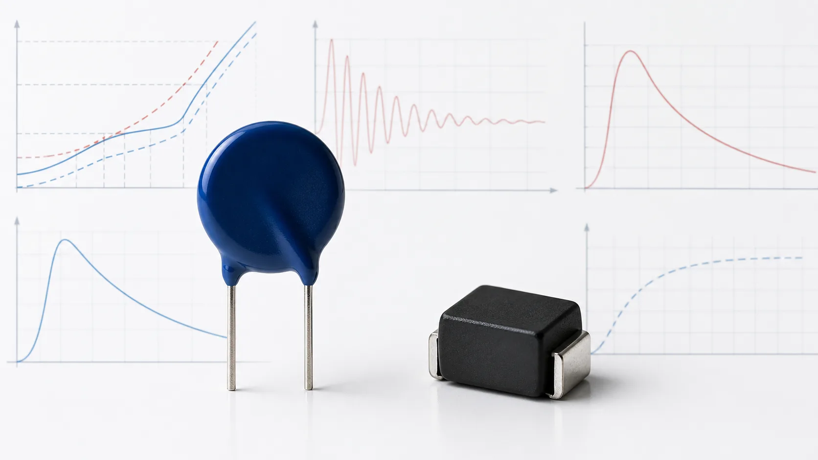
An MOV datasheet may list several voltages, peak current, energy, power, capacitance and leakage. These values describe different operating regions and test conditions. Treating them as interchangeable is one of the most common causes of poor varistor selection.
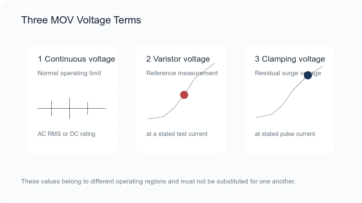
The three most important voltage terms are different: maximum continuous operating voltage defines normal use, varistor voltage is a reference measurement at a small specified current, and clamping voltage is the residual voltage during a much larger pulse.
1. Maximum Continuous Operating Voltage
The maximum continuous operating voltage is the highest voltage that may remain across the MOV under specified conditions. Datasheets commonly provide separate alternating-current root-mean-square (AC RMS) and direct-current (DC) limits.
Use the highest normal circuit voltage, not the nominal supply. Include line tolerance, charging voltage, regulation error, regeneration, temperature and expected abnormal states. Operating too close to the nonlinear region increases leakage and long-term stress.
2. Varistor Voltage
Varistor voltage is measured at a defined DC current. Many disc MOV families use 1 milliampere (mA), while smaller components may use another test current. The datasheet may show a nominal value and tolerance band, such as ±10%.
This is a production reference point on the voltage-current curve. It is not the normal operating voltage and it is not the voltage the load will see during a surge.
3. Clamping Voltage
Clamping voltage is the maximum residual voltage across the MOV at a stated pulse current and waveform. It must always be read together with that current. A clamping value at 1 A cannot be compared directly with a value at 25 A, 100 A or 1 kA.
As current rises, the MOV voltage also rises because the device has a finite dynamic resistance. At high current, bulk resistance, electrodes, terminations and circuit inductance become increasingly important.
Why the Three Voltages Cannot Be Substituted
| Term | Where it applies | Main design question |
|---|---|---|
| Maximum continuous voltage | Normal operation | Will the MOV remain stable without excessive leakage? |
| Varistor voltage | Reference current on the nonlinear curve | Is the production voltage window correct? |
| Clamping voltage | High-current transient | Will the downstream circuit survive the residual voltage? |
4. Peak Surge Current
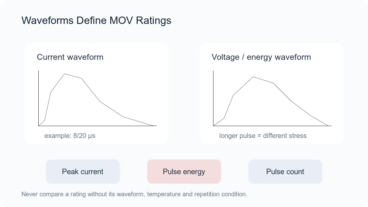
Peak surge current is the maximum current under a specified pulse waveform, commonly 8/20 μs for many MOV products. It is often a one-time or small-number-of-pulses maximum. The first number describes the approximate rise time and the second the decay to half value under the standard definition.
Do not apply an 8/20 μs current rating to a longer pulse without supporting data. A longer event can deposit much more energy even at a lower peak current.
5. Energy Rating
Energy is measured in joules and tied to a stated waveform and test method. It represents the electrical energy absorbed during the pulse, but the headline value does not describe temperature rise, repetition or service life by itself.
For a known time-varying voltage and current, pulse energy is the integral of voltage multiplied by current over time. Use the actual waveform or a validated approximation. Check the manufacturer’s test condition before comparing energy values between series.
6. Pulse Endurance and Repetition
Many datasheets provide curves for the allowable current versus pulse duration and number of pulses. These are often more useful than the maximum single-pulse rating. The allowable current normally falls as pulse duration or pulse count increases.
A design that passes one surge may still age during repeated field events. Define expected pulse count and interval, then check post-test leakage and varistor-voltage shift when reliability is important.
7. Rated Power
Rated power describes allowable continuous or average dissipation under specified ambient and mounting conditions. It should not be confused with pulse energy. Repetitive events can create average heating even when each individual pulse is below the single-pulse limit.
If abnormal voltage can hold the MOV in conduction, calculate the resulting power and ensure a fuse, thermal disconnect or other protective action removes the fault safely.
8. Leakage Current
Leakage is the current below the main nonlinear conduction region. It depends strongly on applied voltage and temperature and can increase after overstress. Leakage affects standby power, battery life, high-impedance measurements and thermal stability.
Compare leakage at the actual operating voltage and temperature. A maximum value at one voltage cannot be moved to another operating point without the voltage-current curve.
9. Capacitance
MOV electrodes and ceramic form a capacitance. Through-hole disc MOVs and standard multilayer varistors can have significant capacitance, while specialized low-capacitance products are available for signal interfaces.
Check the measurement frequency and bias. On high-speed lines, validate signal integrity, insertion loss or eye margin. On power lines, capacitance is usually less critical but may affect electromagnetic-interference behavior.
10. Response and Inductive Overshoot
The intrinsic nonlinear response of an MOV is fast, but the first voltage overshoot at the load often depends on connection inductance. A long trace creates additional voltage proportional to the rate of change of current.
Place the MOV near the transient entry point and keep the current loop short. Measure at the protected load as well as at the MOV terminals.
11. Temperature Derating
Continuous voltage, current, energy or power may require derating above a stated temperature. Leakage also rises with temperature. Use the series-specific curves and consider local heating, enclosure temperature and neighboring power components.
12. Tolerance and Voltage-Current Curves
A nominal varistor voltage may have a broad tolerance. The lowest device in the band must not conduct excessively during normal operation, while the highest device must still clamp below the load limit.
Use maximum and minimum voltage-current curves when available. A single typical curve is not enough for worst-case protection analysis.
13. Package, Size and Termination
Disc diameter or surface-mount case size influences active volume, thermal mass and assembly, but it is not an electrical specification by itself. Confirm body dimensions, lead spacing or land pattern, termination material, soldering process, coating and mechanical reliability.
14. Qualification and Safety Evidence
AEC-Q200, Underwriters Laboratories (UL) recognition, International Electrotechnical Commission (IEC) test references and environmental declarations address different requirements. None replaces application-specific validation. Confirm that the exact part number—not only the product family—has the required evidence.
How to Read an MOV Datasheet in Order
- Confirm maximum continuous AC or DC voltage.
- Read varistor-voltage test current and tolerance.
- Find clamping voltage at the relevant current.
- Check the full maximum voltage-current curve.
- Match peak current and energy to the actual waveform.
- Use repetitive-pulse and temperature-derating curves.
- Review leakage, capacitance, power and failure coordination.
- Confirm package, qualification and safety evidence.
Frequently Asked Questions
Is varistor voltage the same as clamping voltage?
No. Varistor voltage is measured at a small reference current. Clamping voltage is measured during a larger transient current and is higher.
Is maximum continuous voltage the same as rated voltage?
“Rated voltage” can be ambiguous. Use the exact datasheet term and distinguish AC RMS, DC continuous voltage, varistor voltage and test conditions.
Can energy ratings be compared directly?
Only when waveform, test method, temperature and repetition are comparable. A joule value without its pulse condition is incomplete.
Why does clamping voltage rise with current?
The MOV is nonlinear but not an ideal voltage source. Its dynamic resistance and internal series resistance create a higher voltage as current increases.
Conclusion
MOV parameters form a connected system. Continuous voltage protects stability during normal operation; varistor voltage describes the reference curve; clamping voltage and surge current describe the transient; energy and endurance describe stress; leakage, capacitance, temperature and package determine practical suitability. Read the conditions together and validate the complete circuit.
Continue with How to Select an MOV or return to MOV Basics.











