

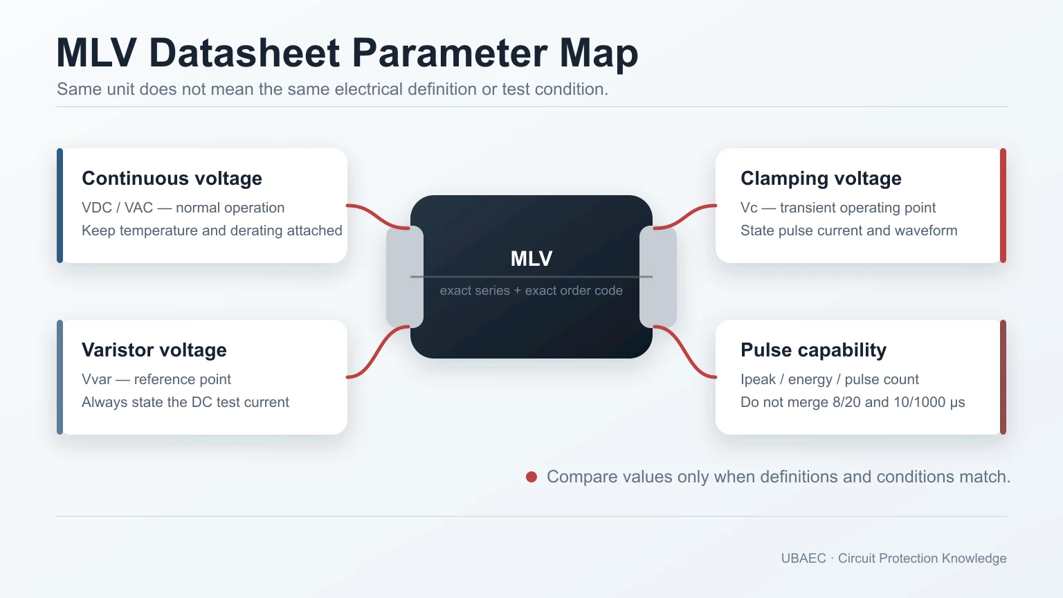
A multilayer varistor (MLV) datasheet contains several voltages, currents and pulse ratings that answer different questions. The most common selection error is to compare numbers that share a unit but not a definition or test condition.
Core rule: a value is comparable only when the field meaning, construction, test current or waveform, frequency, temperature, repetition and part scope match.
The Three Voltage Fields That Must Stay Separate
| Field | Meaning | Required companion conditions | Not interchangeable with |
|---|---|---|---|
| Maximum continuous voltage (VDC or VAC) | Normal voltage the part may withstand continuously under stated conditions | Direct-current (DC) or root-mean-square alternating-current (AC) basis, frequency where relevant, temperature and derating | Vvar, Vc or a leakage-test voltage |
| Varistor voltage (Vvar, V1mA, V0.1mA or supplier symbol) | Reference voltage measured at a specified low DC current | Test current, polarity, tolerance, temperature and method | Continuous operating voltage or surge clamping voltage |
| Clamping voltage (Vc) | Voltage measured during a stated transient current | Clamp current, waveform, polarity, source/setup and temperature | Vvar or a fixed universal ceiling |
Never infer VAC from VDC through a universal ratio. Never display Vc without its current and waveform. A lower Vc measured at a lower current is not automatically better than a higher value measured under a more severe condition.
Parameter Reference
Maximum continuous DC and AC voltage
VDC,max and VAC,max define normal-use ceilings, not trigger points. Include supply tolerance, charging conditions, ripple, temporary overvoltage, temperature and life/derating rules. AC ratings use an RMS basis and must come from the exact product data.
Varistor-voltage range and tolerance
A nominal Vvar may have a percentage tolerance or explicit minimum/maximum limits. Compare nominal with nominal or worst case with worst case at the same test current. A 1 mA value cannot be treated as the same field as a 0.1 mA or 10 mA value.
Clamping voltage and clamp current
Vc is a paired field: voltage at a defined current and waveform. It represents one point on a dynamic curve. PCB inductance and the real current delivered by the transient can raise the protected-node voltage beyond the datasheet test point.
Maximum peak pulse current
Imax, Ip or a similar symbol states a survivability/stress limit under a defined waveform, event count, interval, temperature and degradation criterion. It is not the same as the current used to specify Vc. One-shot and repetitive-pulse capability remain separate.
Energy rating
An energy value in joules is meaningful only with its pulse shape or duration, repetition, temperature and failure criterion. Do not build a ranking that mixes 10/1000 µs, 2 ms, load-dump or undocumented methods.
Automotive load dump and jump start
Long-pulse energy and temporary-overvoltage conditions are separate from short 8/20 µs surge-current ratings. Not every automotive-qualified MLV is load-dump capable. Match the exact pulse definition, system voltage, event count and model.
Capacitance
Capacitance affects signal integrity and filtering. Record frequency, AC measurement amplitude, DC bias where stated, temperature and whether the number is typical or maximum. A 1 kHz value and a 1 MHz value are not directly comparable.
Leakage current
Leakage must retain applied voltage, temperature, polarity, timing and pre/post-stress state. It matters on battery-powered and high-impedance nodes. A bare microamp value without test voltage is incomplete.
Response or turn-on time
Response-time claims depend on the device, fixture, injection method, bandwidth and threshold definition. Do not publish one universal MLV response time or use it to ignore PCB-path inductance.
Electrostatic discharge (ESD) withstand or dynamic clamp result
Record standard edition, network, contact/air mode, polarity, shot count, setup, measured node and acceptance criterion. An ESD overshoot or dynamic-clamp result is not the same field as surge Vc, and component characterization is not automatic equipment immunity.
Operating and storage temperature
Operating and storage limits are different. Suffix, package, termination and qualification may change the range, and electrical/pulse capability may derate inside it. Do not assume equal performance at every temperature.
Qualification scope
Automotive Electronics Council qualification statements such as AEC-Q200 need the revision, family or order-code scope, temperature grade and manufacturer evidence. Qualification is not an application recommendation and does not prove that a module or vehicle meets its system requirements.
Lifecycle and document revision
Active, not recommended for new designs (NRND) and discontinued status is separate from electrical capability. Recheck the exact order code, region, canonical product source, access date and datasheet revision before publication or design release.
Insertion loss and frequency response
For data-line or filter products, frequency response belongs to the exact topology, fixture impedance, bias and frequency span. It cannot be reconstructed from a single capacitance value or redrawn from a proprietary curve as generic performance.
Waveforms That Must Not Be Merged
| Evidence type | What must remain attached | Unsafe shortcut |
|---|---|---|
| ESD | Network, standard edition, mode, polarity, shots and setup | Convert a kV withstand statement into an 8/20 µs rating |
| 8/20 µs pulse | Peak current, count/interval, temperature and degradation criterion | Infer load-dump or long-pulse energy |
| 10/1000 µs or millisecond pulse | Exact duration/shape, energy and repetition | Compare joules with an unrelated method |
| Automotive pulse/load dump | Pulse definition, source/system voltage, event count and exact model | Infer from AEC-Q200 or a short surge test |
| Installation surge | Generator, source impedance, coupling, system topology and acceptance | Claim equipment compliance from a component rating |
A Matched-Condition Comparison Checklist
- Confirm both candidates are construction-matched MLVs.
- Compare exact current order codes, not a portfolio’s combined extrema.
- Align VDC/VAC basis and temperature/derating.
- Align Vvar symbol, test current and tolerance basis.
- Align Vc current, waveform, polarity and temperature.
- Align Imax/energy waveform, repetition and failure criterion.
- Align capacitance frequency, amplitude/bias and typical/maximum basis.
- Align leakage voltage and temperature.
- Confirm package, termination, lifecycle, revision and qualification scope.
- Mark missing data as not established, not zero, then request evidence or test.
Use How to Select an MLV to turn these fields into a design workflow, and MLV reliability, standards and failure modes to interpret qualification and endurance evidence.
Summary
MLV comparison is an identity-and-conditions problem before it is a numbers problem. Keep continuous voltage, Vvar, Vc, clamp current, Imax, energy, capacitance, leakage, temperature, qualification and lifecycle as separate fields. If a required condition is missing, the safe result is “not yet comparable.”
Continue Reading
- How to Select an MLV
- MLV Reliability, Standards and Failure Modes
- MLV vs TVS Diode
- MLV vs SMD MOV and Disc MOV
Official Technical References
The following first-party, standards-organization or publisher records support the technical boundaries used in this article. Always verify the current revision and the exact product scope before design release.












