

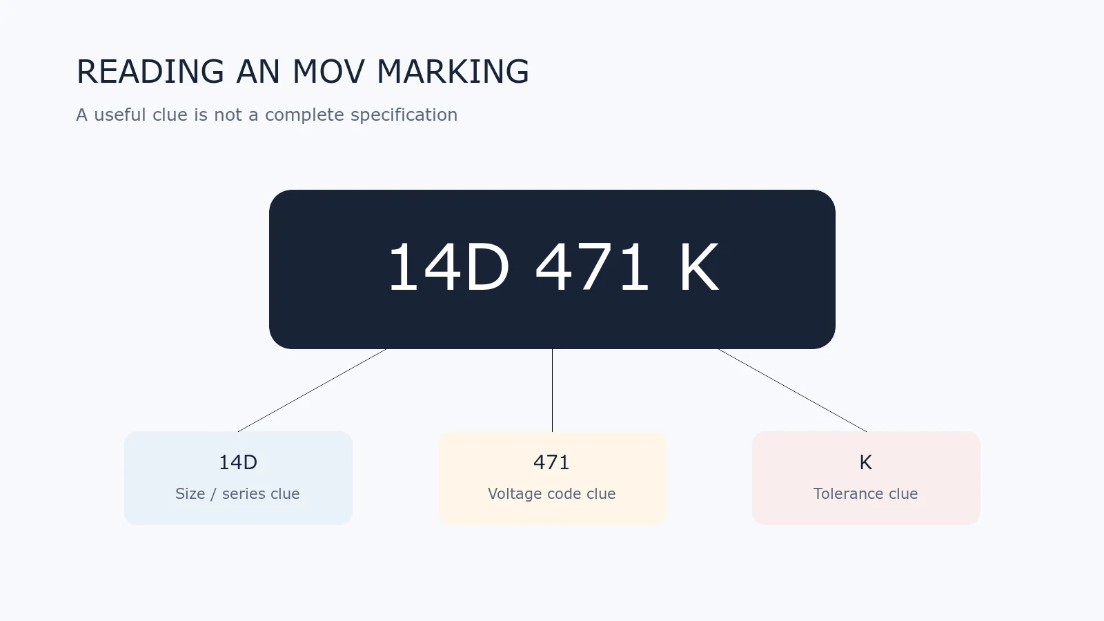
A short code printed on a varistor can look like a complete specification, but it usually is not. The body marking may identify a nominal varistor-voltage code, tolerance, disc size, series, date or production lot. Its meaning depends on the manufacturer and product family.
This Technical Q&A explains how to read common metal-oxide varistor (MOV) markings without turning a useful clue into an unsafe assumption.
What Does 471K Commonly Mean?
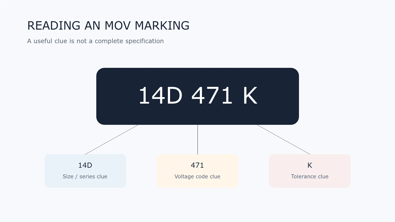
In many radial-disc MOV families, 471 is a three-digit nominal varistor-voltage code. The first two digits are significant figures and the third digit is the decimal multiplier:
47 × 101 = 470 V
The letter K commonly indicates a ±10% tolerance class for the varistor voltage. However, this interpretation must be confirmed in the relevant series datasheet. It does not by itself identify maximum continuous operating voltage (MCOV), clamping voltage, surge current or energy.
Is 470 V the Normal Operating Voltage?
No. The nominal value encoded by 471 normally refers to varistor voltage measured at a specified reference current, often 1 mA for many disc families. It is not the permitted continuous AC or DC voltage.
The operating limit is published separately as maximum continuous AC voltage and maximum continuous DC voltage. See What Is V1mA? and MOV Key Parameters.
What Does a Code Such as 14D471K Suggest?
A code written as 14D471K commonly suggests:
- 14: a nominal disc-diameter class around 14 mm;
- D: a disc-style or series notation;
- 471: nominal varistor-voltage code around 470 V;
- K: a commonly used ±10% tolerance designation.
This is a family-level interpretation, not a universal international code. Lead spacing, coating, surge rating, energy, approvals and temperature range can differ between manufacturers even when the visible code looks similar.
Do 7D, 10D, 14D and 20D Prove Surge Capability?
No. They commonly indicate nominal disc-size classes, and a larger disc often allows a higher energy or surge-current rating within one manufacturer’s related series. But size alone does not prove the rating.
Compare the actual part-number table under the same waveform, pulse count and temperature. A 14 mm device from one series may not match another 14 mm device in construction or performance.
Why Can the Same Voltage Code Have Different MCOV Values?
Voltage codes and MCOV are related but not identical. Manufacturers define product families using their own target characteristics, tolerance, reference current and safety margin. The AC and DC continuous ratings must come from the datasheet row for the complete part number.
How Are Molded SMD MOVs Marked?
A molded surface-mount MOV may have enough top area for a shortened series or package code, voltage identifier, tolerance or lot code. Other products use compact laser marking that cannot be decoded reliably without the manufacturer’s marking table.
Do not infer that every black rectangular device is an MOV. Similar packages are used for transient-voltage-suppression (TVS) diodes, thermistors, resistors and other protection parts. Verify the full ordering code, package drawing and electrical table.
How Are Multilayer Varistors Marked?
Small multilayer varistors (MLVs) may be unmarked because the component body is too small for useful text. Identification then depends on the reel label, packaging, purchase record and bill of materials.
Once loose unmarked chip parts are mixed, visual appearance is usually insufficient to recover the exact voltage, capacitance, package or series.
What Are Date and Lot Codes?
Extra letters or numbers may identify manufacturing date, lot, plant, revision or internal traceability. Their format is manufacturer-specific. A production code should not be mistaken for a voltage or tolerance code.
Can I Replace an MOV With One Carrying the Same 471K Marking?
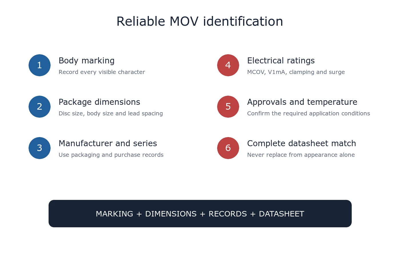
Not from the marking alone. At minimum compare:
- maximum continuous AC and DC voltage;
- nominal varistor voltage and tolerance at the stated test current;
- clamping voltage at the specified surge current and waveform;
- peak current, energy and repetitive-pulse capability;
- disc or package dimensions, lead spacing and mounting method;
- temperature range and derating;
- safety approvals, flammability and application restrictions.
What Should I Record Before Removing a Part?
Photograph the body marking and circuit location, record the equipment model and board reference, measure the package and lead spacing, and keep the original part isolated. If the component is damaged, record the surrounding circuit and fault history before cleaning the board.
Quick Interpretation Table
| Visible item | Possible meaning | What still needs confirmation |
|---|---|---|
| 471 | Nominal varistor-voltage code near 470 V in many series | Reference current, MCOV and complete series |
| K | Commonly ±10% varistor-voltage tolerance | Manufacturer’s tolerance table |
| 14D | Commonly a 14 mm disc class | Actual dimensions, lead spacing and ratings |
| Short extra code | Series, date, lot or plant identifier | Manufacturer marking guide |
| No marking | Common on small MLVs | Reel label, BOM and purchase record |
Related Guides
For help identifying a part, use Ask UBAEC and include clear photographs, dimensions, circuit position, normal voltage and any known manufacturer or ordering information.












