

An MOV is often selected from a nominal rail or mains voltage: 24 V DC, 120 V AC, 230 V AC, and so on. That number is necessary, but it is not the voltage the MOV must merely “match.” The device has to remain stable at the highest voltage that can be present continuously at its actual connection point.
This is why maximum continuous operating voltage—usually shown as MCOV, maximum RMS voltage, or maximum DC voltage—must be checked against the worst-case steady-state condition rather than the nominal label alone. Selecting an MOV with an MCOV equal to the nominal system voltage can place the device too close to its conduction region when the supply rises within tolerance.
Four voltage terms that should not be treated as interchangeable
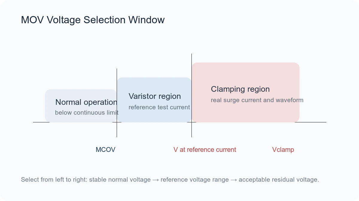
Nominal system voltage is the name of the rail or power system. MCOV is the maximum AC RMS or DC voltage that may be continuously applied under the manufacturer’s stated conditions. Varistor voltage, often specified as V1mA, is measured at a defined test current. Clamping voltage is measured at a defined pulse current and waveform.
V1mA and clamping voltage describe points on the MOV’s nonlinear current-voltage curve. Neither value is the permitted continuous operating voltage. A correct selection process therefore separates normal-state stress from transient-state protection.
What raises the actual continuous voltage?
Supply tolerance and high-line operation
A 230 V AC system with a permitted +10% high-line condition can reach 253 V AC continuously. In a TDK SIOV calculation example, this leads to a 275 V AC varistor class as the nearest class above the required operating voltage. This is a method example, not a universal recommendation for every 230 V product. Regional supply rules, product standards, abnormal operating conditions, and the protected circuit’s withstand level still have to be checked.
The MOV connection point
The voltage across an MOV depends on whether it is connected line-to-line, line-to-neutral, line-to-ground, or across a DC rail. In three-phase equipment, wye and delta systems can produce different stress across the same physical placement. Littelfuse’s industrial selection guidance explicitly starts with maximum service voltage and the connection scheme before moving to surge current and energy.
DC tolerance, charging, ripple, and regeneration
A DC bus may rise because of regulator tolerance, battery charging, load removal, regenerative energy, or permitted control behavior. Determine the highest voltage that can persist during normal or allowed operation. Do not include the transient that the MOV is intended to suppress in the continuous-voltage calculation; that transient belongs in a separate pulse assessment.
Non-sinusoidal waveforms
RMS voltage alone may hide a high peak in PWM, rectified, or distorted waveforms. TDK’s selection procedure advises comparing non-sinusoidal AC waveforms with the permissible DC operating voltage so that the applied peak or amplitude does not exceed the device limit. The actual waveform therefore matters, not just a multimeter reading.
More MCOV margin is not automatically better protection
A higher-voltage MOV generally reduces the risk of excessive leakage during high-line operation, but it can also increase the protection level. The residual voltage seen by the load depends on the MOV’s V-I characteristic, surge current, pulse waveform, and the inductance of the PCB and connections.
The design target is a voltage window:
- The MOV’s MCOV must be at or above the highest continuous voltage at the installation point.
- The clamping voltage at the expected surge current and waveform must remain below the protected circuit’s allowable transient voltage.
If no device satisfies both limits, increasing the MOV size alone may not solve the problem. The design may need staged protection, a different suppressor technology, added impedance, or a higher-withstand downstream circuit.
A practical MCOV selection workflow
- Define the terminals. State exactly where the MOV is connected and whether the applied quantity is AC RMS, DC, or a non-sinusoidal waveform.
- Find the maximum continuous voltage. Include positive supply tolerance and any permitted sustained operating condition.
- Check waveform peaks. For non-sinusoidal operation, compare the peak or amplitude with the appropriate device limit.
- Shortlist by MCOV. Reject any candidate whose AC or DC continuous rating is below the calculated requirement.
- Check the protection level. Use the expected surge current and waveform—not only the datasheet’s headline value—to evaluate clamping voltage.
- Verify endurance. Review surge current, energy, pulse life, temperature derating, leakage, and failure-protection requirements.
- Validate the assembled circuit. Include fuse or thermal protection coordination, layout inductance, clearances, and representative surge testing.
Common questions
Does every 230 V AC product require a 275 V AC MOV?
No. A 275 V AC class is a common candidate when the maximum continuous line voltage is above 250 V AC, but the final choice depends on the supply specification, connection point, product standard, abnormal-overvoltage requirements, surge environment, and the downstream withstand voltage.
Should MCOV be as close as possible to the operating voltage?
Not by itself. A lower voltage class may provide a lower clamping level, but it may also produce more leakage and aging near high-line operation. The correct device must satisfy both the continuous-voltage and clamping-voltage limits.
Does MCOV indicate surge capability?
No. Surge capability is specified separately through peak current, energy, waveform, pulse duration, repetition, and life-test conditions.
Conclusion
Do not select an MOV by equating its MCOV with the nominal system voltage. First establish the highest continuous voltage across the device, including supply tolerance and the real connection scheme. Then confirm that the same device provides an acceptable clamping level under the expected surge current and waveform.
Related guides: How to Select an MOV, MOV Key Parameters Explained, and MOV Clamping Voltage Explained. For an application review, provide the full operating-voltage range, connection point, surge waveform, expected current, and downstream withstand voltage through the UBAEC contact page.












