

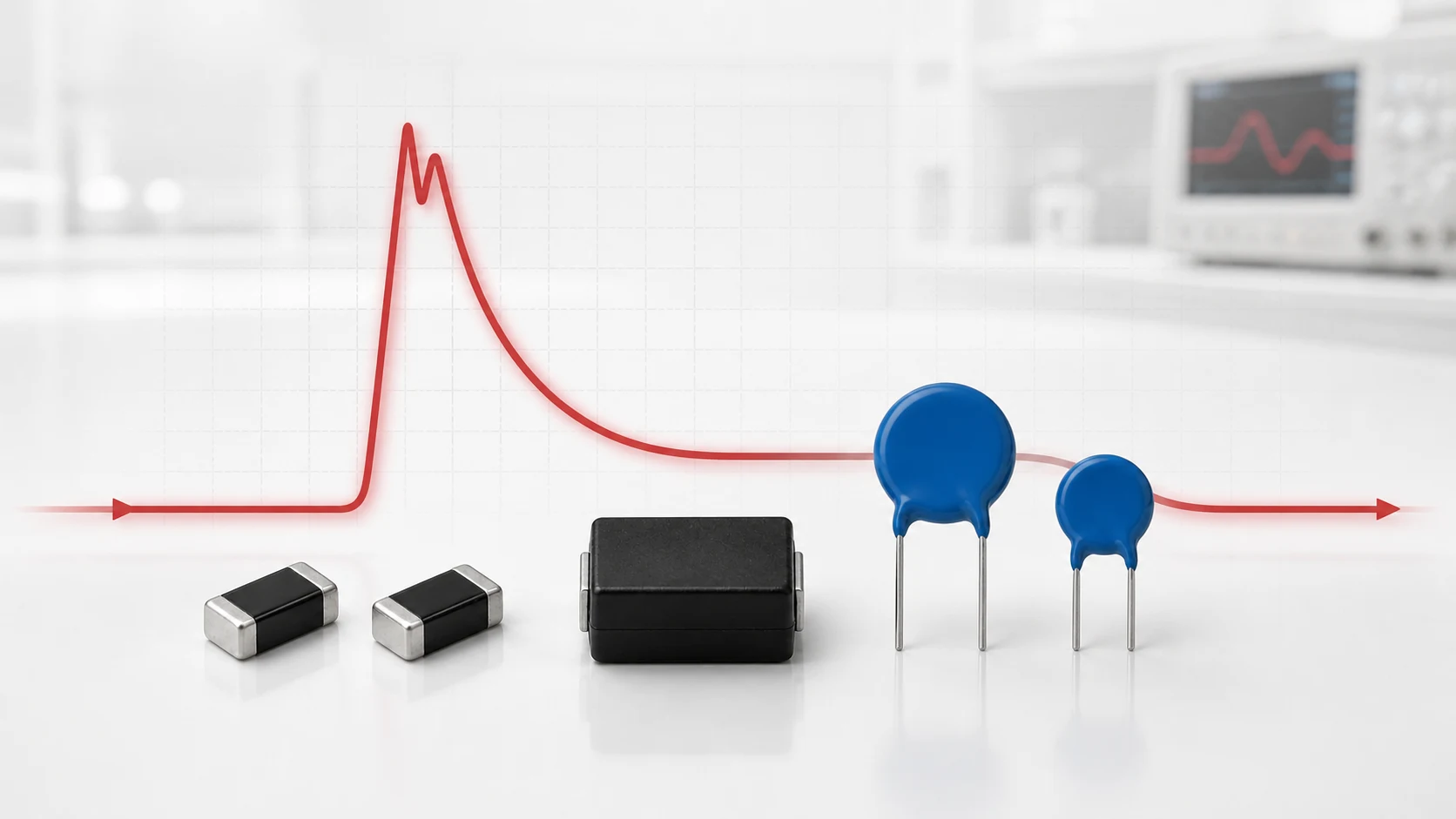
MOV clamping voltage is the voltage that appears across a Metal-Oxide Varistor while a specified surge current flows through it. Datasheets normally state a maximum value at a defined pulse current and waveform. The value is meaningful only when those test conditions are included.
Clamping voltage may also be described as residual voltage or limiting voltage in broader surge-protection discussions. The protected circuit does not automatically see exactly the datasheet number: MOV tolerance, actual current, waveform, temperature, aging and connection inductance all affect the measured result.
How an MOV Clamps a Transient
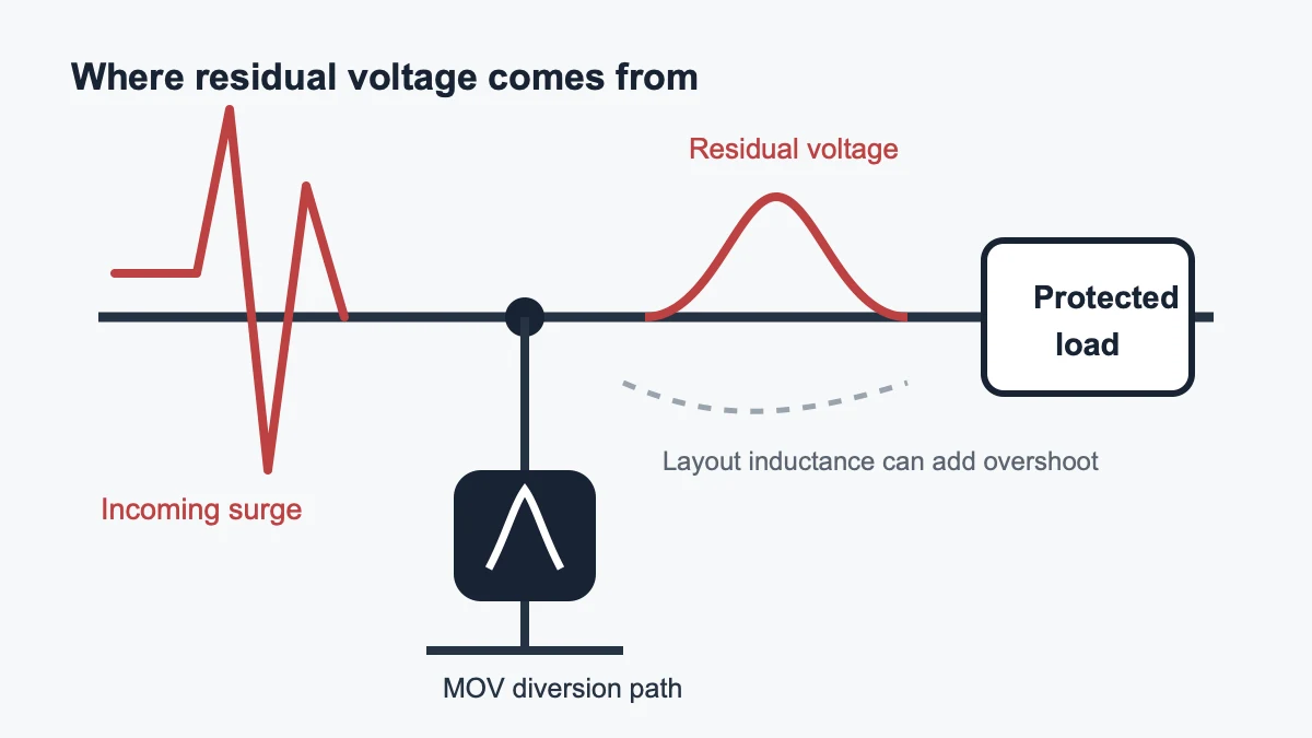
At normal voltage an MOV should remain in a high-resistance state. When a transient pushes the device into its nonlinear region, the MOV conducts current and diverts part of the surge away from the protected load. Its voltage does not become zero or perfectly flat. A residual voltage remains across both the MOV and the protected circuit.
The MOV’s voltage-current characteristic is nonlinear, but it has finite dynamic resistance. Higher current therefore produces a higher voltage. This is why the phrase “this MOV clamps at 710 V” is incomplete unless the current, waveform and limit type are also known.
Always Read Clamping Voltage With Test Current
A datasheet may list maximum clamping voltage at 1 A, 10 A, 25 A, 100 A or another current depending on the package and series. Values at different currents cannot be compared directly.
| Datasheet item | Question to ask |
|---|---|
| Clamping voltage | Is it typical or maximum? |
| Test current | How much current was driven through the MOV? |
| Waveform | Was the current pulse 8/20 μs or another shape? |
| Temperature | At what temperature was the limit specified? |
| Curve | Is the plotted line typical, maximum or tolerance-bound? |
If the expected surge current is not the table’s test current, use the manufacturer’s maximum voltage-current curve when available. Do not scale the clamping voltage linearly from one point.
Why the Pulse Waveform Matters
Many MOV clamping specifications use an 8/20 μs current waveform. The first value describes the standardized virtual front time and the second describes the time to half value on the tail under the waveform definition.
A longer pulse can transfer much more charge and energy even if its peak current is lower. A clamping result measured with 8/20 μs does not automatically predict behavior during a millisecond-scale automotive load dump, a 10/1000 μs telecommunications pulse or a sustained abnormal overvoltage.
Maximum vs Typical Clamping Voltage
A typical curve represents expected behavior and may be useful for simulation or initial comparison. A maximum value includes specified production variation and is normally the safer value for checking protected-load withstand.
Do not combine a typical MOV curve with a minimum load-damage threshold and call the result a worst-case design. Use compatible limits: maximum MOV residual voltage, maximum current, the relevant temperature and layout allowance against the load’s minimum withstand.
The Load May See More Than the Datasheet Value
The clamping voltage in a datasheet is measured at the component terminals under a defined test arrangement. In a real printed circuit board, trace and lead inductance can raise the residual voltage at the protected load by adding a voltage proportional to the rate of change of current:
Vinductive = L × di/dt
A fast surge and a long protection loop can therefore create a brief overshoot at the protected load. Connector inductance, fuse wiring, vias, long MOV leads and probe placement can all change the captured waveform.
- Place the MOV close to the transient entry point.
- Keep the high-current loop short and wide.
- Avoid routing the protected node alongside the incoming surge path.
- Measure at the load and at the MOV terminals during validation.
- Use suitable differential probes and minimize measurement-loop area.
How Source Impedance Changes the Result
The MOV and surge source form a system. Source impedance limits the current that the MOV must divert. A low-impedance source can produce much higher current and therefore a higher residual voltage than a high-impedance source with the same open-circuit voltage.
For an IEC 61000-4-5 equipment test, the generator, coupling network, test level, polarity and port configuration determine the stress delivered to the equipment under test. Do not convert the generator’s open-circuit voltage directly into MOV current without modeling or measurement.
Coordination With the Protected Circuit
A useful protection window must satisfy two conditions:
- The MOV remains stable at the highest continuous operating voltage.
- The maximum residual voltage at the load remains below the load’s transient withstand, with margin.
If one MOV cannot satisfy both conditions, consider a coordinated network. A larger MOV or surge protective device may absorb the high-energy front end, while a TVS (Transient Voltage Suppression) diode, MLV or filter stage provides a lower residual level closer to a sensitive circuit. Series impedance and spacing must be engineered rather than added arbitrarily.
Temperature, Aging and Repetition
Repeated surges can shift varistor voltage, increase leakage or alter clamping behavior. High ambient temperature also affects leakage and thermal margin. The headline one-pulse rating is not a lifetime guarantee.
Use repetitive-pulse curves, derating information and post-test limits. For safety-critical or high-availability equipment, validate the complete protection path after the required pulse count, temperature exposure and abnormal-voltage tests.
Worked Reading Example
Assume a datasheet states a maximum clamping voltage of 710 V at 25 A using an 8/20 μs current pulse. This tells you that the MOV terminal voltage should not exceed 710 V under that specific rated test condition. It does not tell you:
- the voltage at 100 A;
- the voltage during a 10/1000 μs pulse;
- the load voltage with 20 cm of wiring;
- the behavior after repeated surges; or
- whether the protected circuit can survive 710 V.
Each missing condition must be checked before the number is used in a design decision.
Common Clamping-Voltage Mistakes
- Comparing clamping values measured at different currents.
- Using varistor voltage as if it were clamping voltage.
- Using a typical curve as a guaranteed maximum.
- Ignoring the surge source impedance.
- Ignoring PCB and lead inductance.
- Checking only the MOV terminal voltage instead of the load voltage.
- Assuming a one-pulse result guarantees repetitive endurance.
Frequently Asked Questions
Is a lower clamping voltage always better?
Not by itself. A lower-voltage MOV may have higher leakage or excessive stress at the normal operating voltage. The correct device must satisfy both continuous-voltage stability and transient protection.
Can two datasheets be compared using only the clamping-voltage column?
No. Confirm the test current, waveform, temperature, tolerance, package and whether the value is typical or maximum.
Why is the oscilloscope peak higher than the datasheet value?
Possible causes include higher actual current, connection inductance, probe loop error, different waveform, device tolerance, temperature or prior damage. Measure current and voltage simultaneously with an appropriate setup.
Conclusion
MOV clamping voltage is a conditional result, not a fixed switching threshold. Read it with current, waveform and limit type; include source impedance, tolerance, temperature, aging and layout; and validate the residual voltage at the protected load.
Continue with What Is V1mA?, MOV Key Parameters Explained, or MOV vs TVS Diode.












