

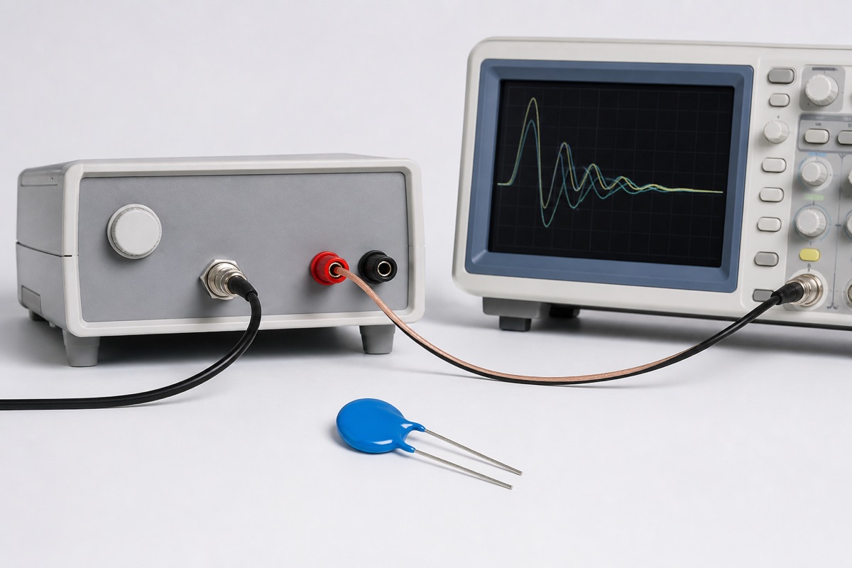
A datasheet may advertise a 6 kA maximum surge-current rating. That does not mean the MOV can absorb 6 kA every time the circuit sees a transient. The number normally belongs to a defined current waveform, pulse count, temperature, and test method.
For repetitive service, the useful question is not “What is the largest number in the table?” It is “What current is permitted at this pulse width and required number of operations?” That answer usually comes from the manufacturer’s pulse-rating or derating curves.
Read the conditions attached to peak current
A peak-current rating is meaningful only with its waveform. An 8/20 μs current pulse, a 10/1000 μs pulse, a rectangular pulse, and a field waveform with the same peak can deposit very different energy in the MOV. The label 8/20 μs describes standard front and tail timing; it is not a generic substitute for every short transient.
Pulse count matters separately. Some tables publish one-pulse and two-pulse ratings. More complete datasheets include families of curves for 1, 2, 10, 100, 1,000, or more operations. The permissible current normally falls as the required number of pulses increases.
Why repetitive pulses require derating
Thermal recovery may be incomplete
Each conduction event dissipates energy inside the varistor body. If the next pulse arrives before the device returns to its initial temperature, heat accumulates. Repetition interval, ambient temperature, mounting, and average power therefore matter in addition to the energy in one pulse.
Pulse loading consumes reliability margin
An MOV is not an ideal clamp with unlimited cycle life. Repeated electrical and thermal stress can change varistor voltage and leakage. Pulse-rating curves treat the number of operations as a design variable because a one-time withstand point is not an intended continuous operating point.
Field waveforms must be converted carefully
TDK’s SIOV selection procedure describes converting a real surge-current waveform to an equal-area rectangular pulse while retaining the peak. The resulting equivalent pulse width can then be compared with the device’s derating curve. The method illustrates why two pulses with the same peak but different duration cannot be treated as equivalent.
What a manufacturer example shows
In one TDK SIOV calculation example, an S14K275 is evaluated at roughly 1,590 A with an 8/20 μs waveform. The published curve permits that stress for only two operations; for ten operations, the permissible current is about 1,000 A. The example then moves to a higher-capability S20 series. These figures apply only to the named family and stated conditions, but the design lesson is general: pulse count changes the acceptable current.
A practical review sequence
- Define the event. Record peak current, waveform, source impedance, polarity, required pulse count, and minimum interval.
- Identify the datasheet reference. Confirm whether the headline current is a one-pulse, two-pulse, or repetitive rating and note the test temperature.
- Normalize the waveform. Use the manufacturer’s method for an equivalent pulse width; do not invent a conversion rule.
- Read the correct curve. Use the required number of operations, not the most favorable curve.
- Check independent limits. Verify energy, average power, temperature derating, clamping voltage, and failure protection.
- Validate the assembly. Include source impedance, PCB inductance, thermal conditions, and protective disconnects in representative testing.
Where the conclusion stops
If a datasheet provides only a headline surge-current value and no repetitive-pulse information, do not extrapolate a cycle-life claim. Ask the manufacturer for the applicable curve or use a more conservative, testable requirement. Curves are series-specific; they cannot be transferred between MOVs merely because their MCOV or voltage code looks similar.
FAQ
Can a two-pulse rating be divided to estimate ten pulses?
No. The relationship is not a simple linear division. Use the published curve for the exact series or obtain manufacturer guidance.
Is staying below the joule rating sufficient?
No. Peak current, waveform, clamping voltage, pulse count, interval, temperature, and average power can impose separate limits.
What if the field transient is not 8/20 μs?
Apply the manufacturer’s waveform-conversion method or use data specified for the actual waveform. Validate with representative source impedance when the conversion is uncertain.
Practical conclusion
An MOV’s single-pulse surge-current rating is one defined test point, not a repetitive-duty guarantee. Repetitive selection requires the device-specific pulse curve plus checks for energy, thermal recovery, average power, clamping behavior, and end-of-life protection.
Continue with MOV Surge Waveforms Explained, MOV Key Parameters, and How to Select an MOV. For a device review, send the waveform, source impedance, peak current, pulse count, interval, and ambient conditions through the UBAEC contact page.












