

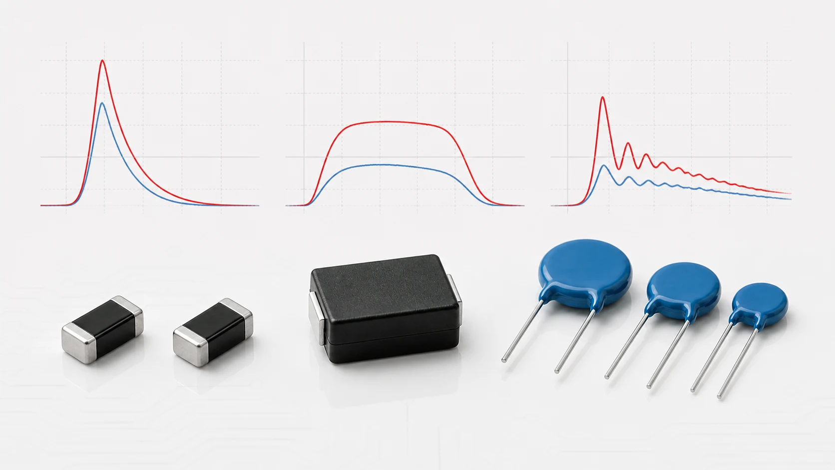
A surge rating is incomplete without its waveform. The same peak current can produce very different charge, energy, heating and material stress when the pulse duration changes. This is why an MOV (Metal-Oxide Varistor) rated for a high 8/20 μs peak current cannot automatically carry the same peak current during a 10/1000 μs pulse or an automotive load dump.
Three terms are often mixed together: the 8/20 μs component current waveform, the longer 10/1000 μs current waveform, and the IEC 61000-4-5 equipment-level surge immunity test. They are related to transient protection, but they are not interchangeable specifications.
What Do Waveform Numbers Mean?
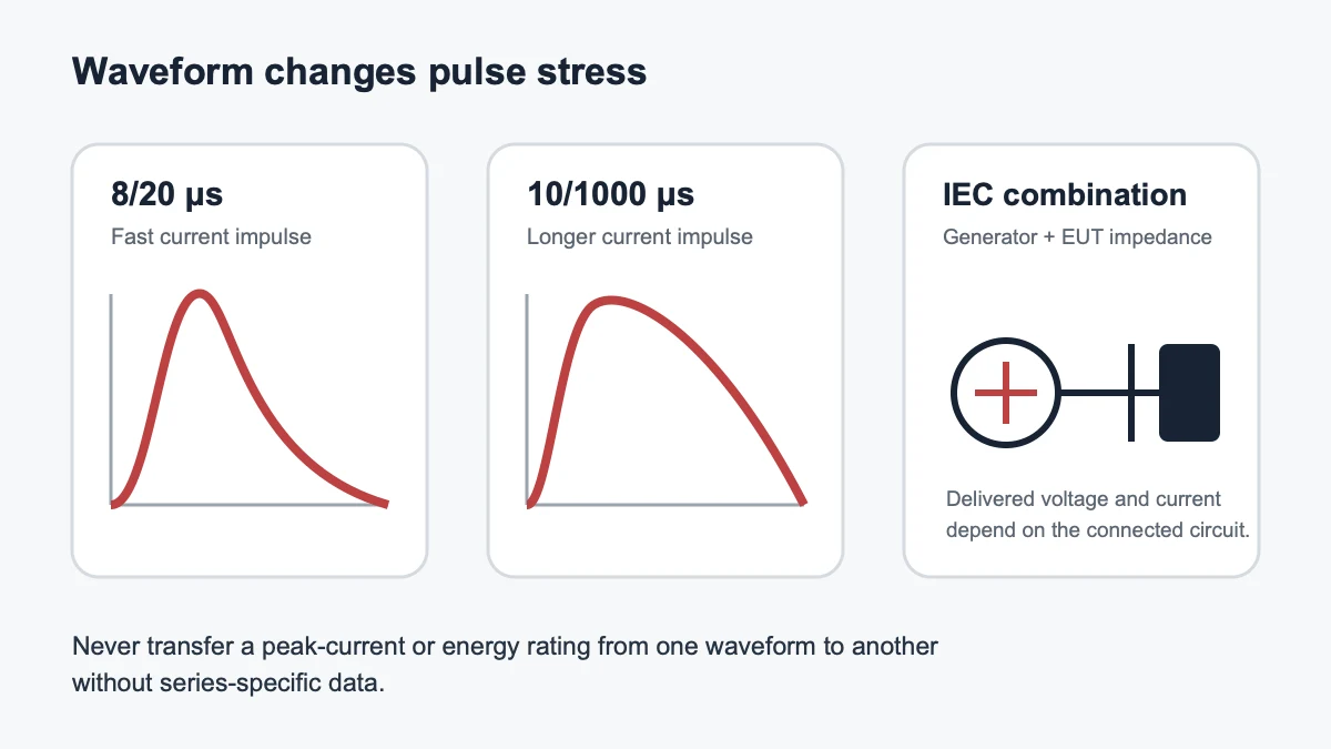
Impulse waveforms are defined using standardized timing rules rather than by a simple visual width. For a current waveform written as 8/20 μs, the first number represents a standardized virtual front time and the second represents the time to half value on the tail. Exact definitions depend on the relevant standard or datasheet.
The notation does not mean that the current is constant for 8 μs and then stops at 20 μs. It describes a fast-rising, decaying impulse. Always use the waveform definition associated with the cited test method.
8/20 μs Current Waveform
The 8/20 μs current waveform is widely used for MOV clamping-voltage tests, peak surge-current ratings and pulse-endurance curves. Many radial MOV and power-oriented SMD MOV datasheets state peak current using this waveform.
Its relatively short duration allows high peak currents, but the result is still tied to pulse count, polarity, interval, temperature and device condition. A “10 kA MOV” normally means a specified maximum under stated 8/20 μs conditions, not a continuous-current capability and not a universal transient rating.
10/1000 μs Current Waveform
The 10/1000 μs waveform has a much longer tail and is commonly encountered in telecommunications and component pulse-power specifications. At the same peak current, it generally delivers substantially more charge and energy than an 8/20 μs pulse.
Do not translate an 8/20 μs current rating into a 10/1000 μs rating using only the ratio of the time numbers. MOV voltage changes during the pulse, thermal diffusion matters and each manufacturer may provide specific pulse-rating curves or separate limits.
IEC 61000-4-5 Combination-Wave Testing
IEC 61000-4-5 is an equipment immunity standard for unidirectional surges associated with switching and lightning effects. It defines test levels, generators, coupling and decoupling networks, setups and procedures for evaluating the response of equipment under specified operating conditions.
For many power-port tests, the combination-wave generator is characterized by a 1.2/50 μs open-circuit voltage waveform and an 8/20 μs short-circuit current waveform. The actual voltage and current delivered to the equipment depend on generator impedance, coupling network and the impedance of the equipment under test.
The standard also addresses other arrangements for specific ports, including a 10/700 μs combined-wave generator for certain lines. Therefore “IEC surge” is not one universal waveform or one universal source impedance.
Component Rating vs Equipment Immunity
An MOV datasheet rating describes the component under a stated component test. An IEC 61000-4-5 result describes how complete equipment behaves in a defined system test. Passing one cannot be inferred from the other without circuit analysis and validation.
| Specification | What it describes | What is still missing |
|---|---|---|
| MOV peak current at 8/20 μs | Component pulse capability under stated conditions | Equipment current division, residual voltage, repetition and layout |
| MOV energy in joules | Absorbed energy under a stated pulse | Other waveforms, temperature rise and lifetime |
| IEC 61000-4-5 test level | Equipment immunity test environment | Exact component stress until the circuit is analyzed or measured |
Why Equal Peak Current Does Not Mean Equal Stress
Instantaneous electrical power is the product of voltage and current. Pulse energy is the time integral of that power. A longer waveform gives the MOV more time to absorb energy and heat internally.
Two pulses with the same peak current can therefore produce different:
- absorbed energy;
- charge transfer;
- peak and average temperature;
- varistor-voltage shift;
- leakage-current change; and
- mechanical or coating stress.
Pulse Count and Interval Matter
A single-pulse maximum is not the same as a repetitive-pulse capability. Datasheets may provide curves for one pulse, two pulses, ten pulses or many pulses, often with a minimum interval that allows cooling.
Real equipment may experience repeated switching events, seasonal lightning exposure or bursts during qualification. Define expected pulse count and interval, then use the appropriate endurance curve and post-test criteria.
Polarity and AC Operation
Standard MOVs are approximately bidirectional, but test procedures still specify pulse polarity and sequence. For line-to-line and line-to-earth tests, polarity, phase angle and coupling path can change the stress on the MOV and neighboring components.
In AC circuits, the normal mains voltage is present before and after the surge. If the MOV becomes damaged or enters thermal runaway, coordinated fusing or a thermal disconnect may be needed to remove it safely.
How to Choose the Relevant Waveform
- Identify the transient source: lightning-induced surge, inductive switching, load dump, electrostatic discharge or another event.
- Identify the applicable equipment or industry standard.
- Record waveform, source impedance, test level, polarity, coupling mode and pulse count.
- Estimate or measure the current through the MOV, not only the generator voltage.
- Read the MOV’s clamping, current, energy and repetitive-pulse data for a comparable waveform.
- Check maximum residual voltage at the protected load.
- Validate temperature, aging, fuse coordination and failure behavior.
Waveforms That Must Not Be Substituted
- Do not use an 8/20 μs rating as a 10/1000 μs rating.
- Do not use a 2 ms energy value as a universal joule limit.
- Do not use an IEC generator’s open-circuit voltage as the voltage that must appear across the MOV.
- Do not use an electrostatic-discharge voltage level as an energy comparison with an IEC surge test.
- Do not use disc-MOV data to claim the capability of an MLV or molded SMD MOV.
Frequently Asked Questions
Is 8/20 μs a voltage waveform or a current waveform?
In MOV datasheets it most commonly identifies a surge-current waveform. In an IEC combination-wave generator, the short-circuit current is characterized as 8/20 μs while the open-circuit voltage is characterized as 1.2/50 μs.
Is 10/1000 μs always more severe?
It is longer and can carry much more energy at the same peak current, but severity depends on amplitude, source impedance, MOV voltage, pulse count and the complete test definition.
Does a 10 kA MOV guarantee a product will pass IEC 61000-4-5?
No. The current through the MOV, residual voltage, circuit layout, coupling mode, other protection stages and the required equipment performance criterion must all be evaluated.
Conclusion
A waveform is part of the rating. Read peak current, front and tail times, energy, repetition and source impedance together. Then connect the component data to the actual equipment-level test through circuit analysis and measurement.
Continue with MOV Clamping Voltage Explained, How to Select an MOV, or send the intended test condition through Ask UBAEC.












