
UBAEC | Electronic Components & Application Insights
  • Components
  • Applications
  • Wiki
    • Submit a Technical Question
  • Technical Topics
  • Industry News
No Result
View All Result
  • MOV
  • MLV Knowledge Map
UBAEC | Electronic Components & Application Insights
  • Components
  • Applications
  • Wiki
    • Submit a Technical Question
  • Technical Topics
  • Industry News
No Result
View All Result
UBAEC | Electronic Components & Application Insights

TDK Introduces High-Surge Multilayer Varistors: Ratings and Selection Limits

Viki by Viki
2026-09-07
in Industry Insights
A A
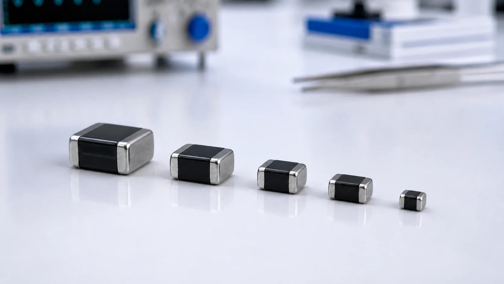
Multilayer varistors in several chip sizes with black glass-ceramic bodies and silver end terminations
Share on FacebookShare on Twitter

TDK Electronics has announced a high-surge multilayer-varistor series developed with a new ceramic material. The company presents the range as a compact option for higher-energy overvoltage protection, extending the usual discussion of MLVs beyond low-energy ESD protection.

Published headline ratings

Parameter Published range or limit
Case sizes EIA 1210 to 2220
Maximum DC operating voltage Up to 65 V DC
Varistor voltage at 1 mA Up to 85 V
Surge-current capability Up to 1 × 5000 A and 10 × 3500 A, 8/20 μs
Clamping voltage Maximum 135 V at 200 A for the cited new-ceramic example
Energy absorption Up to 15,000 mJ at 2 ms
Maximum operating temperature Up to +125 °C

These values describe the top end of a product family, not one universal part. A smaller case size or different voltage option may have substantially different surge, energy, clamping and capacitance data.

Why the announcement matters

MLVs are often associated with compact ESD protection on signal and low-voltage power lines. A family offering higher 8/20 μs surge-current capability may open additional board-level protection options where space is limited. It does not mean that an MLV automatically replaces a larger disc MOV, a TVS diode or a coordinated surge-protection network.

What engineers should verify

  • The exact part number and its maximum continuous voltage under worst-case conditions.
  • Clamping voltage at the relevant current, waveform and temperature.
  • Single-pulse versus repetitive surge capability and the required interval between pulses.
  • Energy rating, pulse duration and temperature derating.
  • Capacitance, leakage and signal-integrity limits when the device is used near data or RF paths.
  • Package land pattern, soldering profile, board-flex risk and transient-current return path.
  • Qualification, safety status and final-system surge or ESD test requirements.

Reference: TDK Electronics: Compact and robust overvoltage protection, 2026-07-16

Next Post
Metal oxide varistor with a thermocouple on a temperature test fixture

How Should MOV Temperature Derating Be Applied?

Line fuse, metal oxide varistor, and thermally coupled cutoff on a small circuit board

Can a Fuse Replace an MOV Thermal Disconnect?

  • Trending
  • Comments
  • Latest
Blue radial metal-oxide varistors used for transient overvoltage protection

What Is a Varistor? MOV Basics and Key Parameters

2026-09-07
Populated electronic circuit board on a laboratory test bench

What Are Electronic Components? Common Types, Functions and Selection Basics

2026-09-07
Conceptual MLV operating regions from normal leakage through transient conduction to post-pulse recovery

How Multilayer Varistors Work

2026-09-07
IEC 61000-4-5 combination-wave surge test chain from generator through coupling network to equipment under test

IEC 61000-4-5 Surge Test Explained: Waveforms, Coupling and Interpretation

2026-08-10
Populated electronic circuit board on a laboratory test bench

What Are Electronic Components? Common Types, Functions and Selection Basics

1
Oscilloscope probes measuring surge residual voltage between the protected node and local return after an MOV

Why Do MOV Leads and PCB Traces Increase Residual Voltage?

1
Blue radial metal-oxide varistors used for transient overvoltage protection

What Is a Varistor? MOV Basics and Key Parameters

0
Multilayer chip varistors and molded surface-mount MOV packages used for circuit protection

What Is an SMD MOV? Types, Parameters and Applications

0
GDT devices with a surge generator and oscilloscope in a circuit-protection test setup

Why Can a GDT Keep Conducting After a Surge?

2026-09-16
Single two-terminal MLCC in a measurement fixture with a completed thermal-history backdrop and a conceptual slow downward time trend

MLCC Aging and De-Aging: Capacitance After Reflow and Referee Time

2026-09-15
Disc MOV on a test fixture with a thermal image and a time-voltage withstand curve

How to Read MOV TOV Data: Temporary Withstand Is Not MCOV

2026-09-14
Three-lead thermally protected MOV connected to a status LED and optocoupler test board

How Should the Third Lead of a Thermally Protected MOV Be Wired?

2026-09-13

Need help selecting a component?

Share the operating voltage, package, surge or ESD conditions. We will help you identify the parameters that matter.

Submit a technical question

About UBAEC

UBAEC provides electronic component information, circuit protection knowledge, application guidance, and inquiry support for engineers and sourcing teams.

Categories

  • Application Notes
  • Automotive
  • Basics
  • Consumer Electronics
  • Cross Reference
  • Downloads
  • Industrial Control
  • Industry Insights
  • LED Lighting
  • Manufacturers
  • MLV
  • Parameters
  • Protection Circuits
  • Selection Guide
  • Standards
  • Technical Q&A
  • Telecommunications

Recent Post

  • Why Can a GDT Keep Conducting After a Surge?
  • MLCC Aging and De-Aging: Capacitance After Reflow and Referee Time
  • About
  • Contact
  • Privacy Policy
  • 中文

© 2026 UBAEC — Electronic Components & Application Insights. All rights reserved.

No Result
View All Result
  • Home
  • Component Center
  • Applications
  • Technical Wiki
  • News
  • Contact

© 2026 UBAEC — Electronic Components & Application Insights. All rights reserved.









