

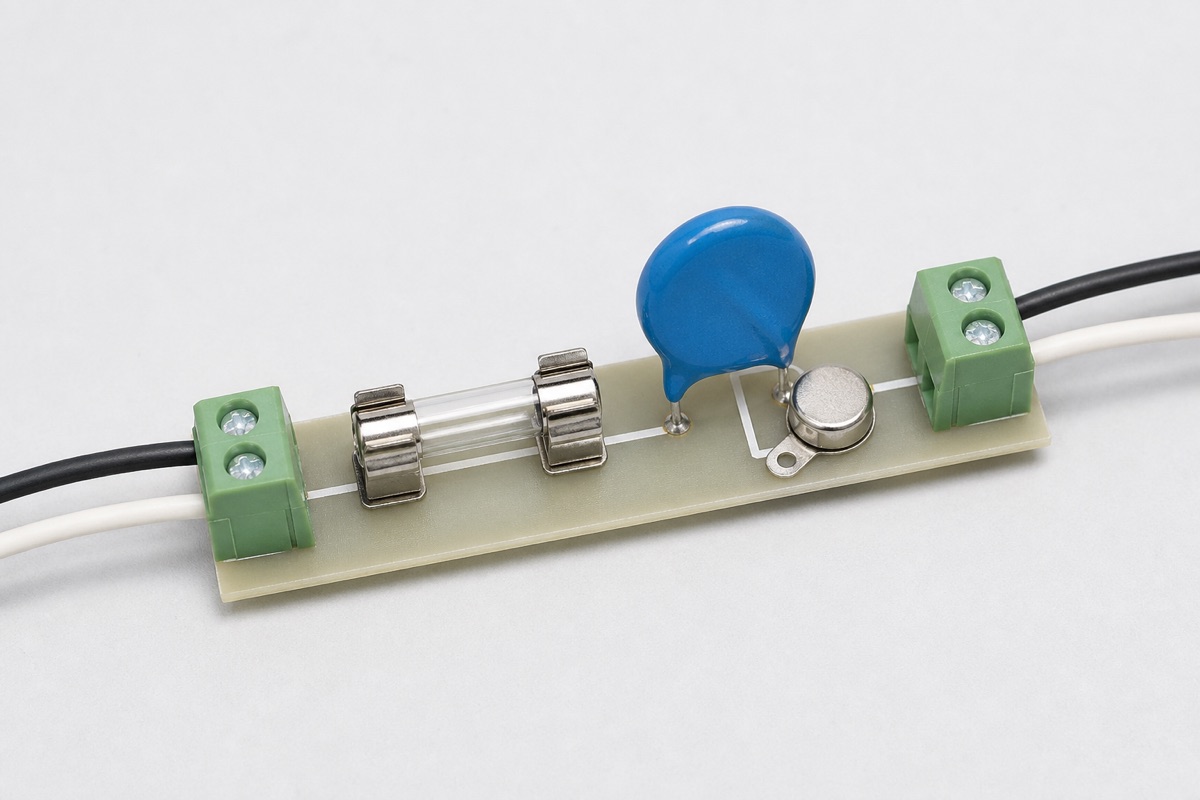
If an AC input already has a fuse, does the MOV still need a thermal disconnect? The fuse does not answer that question by itself. A conventional fuse responds to current over time; a thermal disconnect is intended to remove an MOV when the device itself reaches an unsafe thermal condition. Their sensing mechanisms and fault windows are different.
A sustained abnormal overvoltage can drive enough limited current through an MOV to produce heating without forcing the upstream fuse to open quickly. Conversely, a thermal cutoff is not automatically suitable for interrupting every high-current fault. The devices must be coordinated, not substituted by label.
Three protection functions to keep separate
The line fuse limits overcurrent duration
A fuse operates according to its time-current curve and interrupting rating. It must ride through permitted inrush and surge events while opening under specified faults. A fuse protecting the whole product may be sized above the current that causes local heating in an MOV during a limited-current abnormal overvoltage.
The thermal disconnect responds to MOV temperature
A thermal cutoff or disconnect is positioned and thermally coupled so that MOV heating can trigger isolation. Its effectiveness depends on trip temperature, conductive and radiative heat paths, placement, assembly tolerance, and the safe state after opening.
A thermally protected MOV integrates the critical coupling
Integrated devices combine the varistor and thermal-disconnect mechanism in one package. This can improve repeatability of the thermal path, but it does not remove the need to check MCOV, surge ratings, prospective fault current, monitoring-pin use, approvals, and end-product tests.
Why a standard fuse may not catch MOV overheating
A Littelfuse application note on thermally protected MOVs describes abnormal-overvoltage tests in which the limited current through the MOV can remain below the trip region of a standard line fuse while the MOV continues to self-heat. A thermally coupled cutoff is then used to disconnect the MOV branch. This is a mechanism example, not a universal circuit prescription; the actual voltage, source impedance, standard, and enclosure still control the design.
The reverse distinction also matters. If an MOV fails at low resistance and the available current is high, an appropriately rated fuse or other overcurrent protective device may be needed to clear the fault safely. A thermal element cannot be assumed to replace the line-protection function.
Conditions that must be reviewed together
- Maximum continuous voltage: the MOV must remain stable at the highest normal line condition.
- Abnormal overvoltage: define voltage, source impedance, duration, and resulting limited current.
- Fuse characteristics: include inrush withstand, time-current behavior, and interrupting rating.
- Thermal coupling: verify cutoff location, trip temperature, heat-transfer path, and assembly tolerance.
- MOV failure behavior: consider rising leakage, thermal runaway, short-circuit failure, and adjacent materials.
- Applicable standards: separate component approvals, equipment immunity, and complete-SPD requirements.
A practical coordination workflow
- Define the MOV location, highest normal voltage, and required surge environment.
- List foreseeable sustained abnormal voltages and their source impedances.
- Map the resulting fault current onto the fuse time-current curve.
- Determine whether the fuse opens before the MOV reaches an unsafe temperature across the relevant fault window.
- Where a low-current heating gap remains, evaluate a thermally coupled cutoff or a thermally protected MOV.
- Test surge ride-through, abnormal overvoltage, disconnect behavior, fault clearing, and enclosure temperatures under the applicable product requirements.
FAQ
Can a small fuse placed in series with the MOV solve the problem?
It may help isolate some faults, but it must still survive required surge current and open safely under the expected fault. It does not automatically sense the MOV’s hottest point.
Can the line fuse be removed when a thermal disconnect is used?
That conclusion is generally unsafe. The thermal disconnect addresses an MOV thermal event; line overcurrent, conductor protection, and high-fault-current interruption remain separate requirements.
Is an integrated thermally protected MOV always better?
It can improve thermal-coupling consistency, but voltage range, surge capability, size, cost, monitoring, and approvals may differ. Select it against the complete circuit and test plan.
Practical conclusion
A fuse and an MOV thermal disconnect are not interchangeable. The fuse operates on current and time; the disconnect operates on the MOV’s thermal condition. Reliable protection comes from checking both devices against normal surge ride-through, sustained abnormal overvoltage, available fault current, thermal coupling, and the applicable end-product tests.
Continue with MOV Failure Modes and Thermal Protection, MOV Protection Circuit Basics, and MOV Protection for AC-DC Power Supplies. For a circuit review, send the line range, fuse part number, MOV part number, abnormal-overvoltage conditions, and applicable standard through the UBAEC contact page.












