

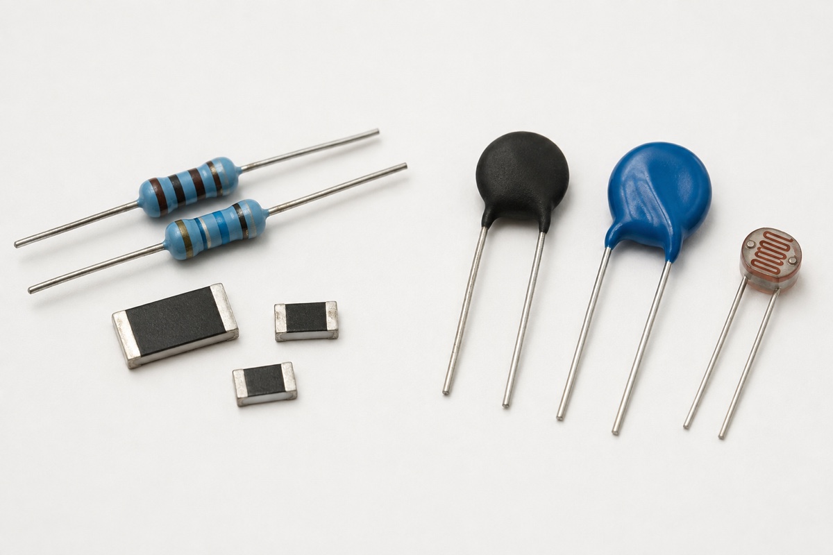
What is the difference between linear and nonlinear resistors? In a linear resistor, current is approximately proportional to applied voltage over the specified operating range, so the ratio R = V/I remains nearly constant when temperature and other conditions are held steady. In a nonlinear resistor, that ratio changes deliberately or substantially with voltage, temperature, light, or another stimulus. A metal oxide varistor (MOV), a negative temperature coefficient (NTC) or positive temperature coefficient (PTC) thermistor, and a photoresistor are therefore not merely fixed resistors with unusual values.
The word “linear” is still an engineering approximation. Every real resistor has temperature coefficient, self-heating, voltage, frequency, and power limits. The correct question is whether its V-I relationship is sufficiently linear for the intended operating region and accuracy, not whether resistance is mathematically constant under every possible condition.
Linear means an approximately straight V-I relationship
For an ideal ohmic resistor, V = I × R and the V-I plot is a straight line through the origin. A practical fixed resistor is treated as linear when changes in applied voltage produce proportional current changes within its rated region and the remaining value shifts fit the circuit’s error budget. IEC 60115-1 nevertheless includes tests and definitions for tolerance, temperature coefficient, overload, endurance, environment, and assembly because real components deviate from the ideal.
Temperature is a major source of movement even in a “linear” resistor. If a 100 Ω part has a specified TCR of +100 ppm/°C, a 50 °C change corresponds to a first-order shift of about +0.5 %, before adding initial tolerance, self-heating, load-life drift, and other effects. This does not automatically make the part a nonlinear resistor; the device may still have an approximately linear V-I curve at each stabilized temperature. It does mean that linear and invariant are not synonyms.
Excessive voltage or power can also move a fixed resistor outside its intended region. Self-heating changes resistance, while overload may cause irreversible drift or failure. The designer must satisfy both rated dissipation after ambient derating and maximum working or limiting-element voltage. A large resistance at low power can exceed its voltage limit before it reaches its nominal wattage.
Voltage-dependent resistors: the MOV case
A varistor is intentionally nonlinear with applied voltage. Below its maximum continuous operating voltage, an MOV normally presents high resistance and limited leakage. As voltage rises into the nonlinear region, current increases much faster and the effective static resistance V/I falls. Connected in parallel with a protected circuit, the MOV diverts transient current and limits the voltage according to its V-I characteristic and the external source and wiring impedance.
TDK’s general technical information describes the MOV characteristic over leakage, nonlinear, and high-current regions. It also shows why one resistance figure is not useful across those regions: the static resistance of one example spans many orders of magnitude between normal operation and overvoltage. IEC 61051-1 accordingly defines varistor-specific quantities rather than treating the device as an ordinary fixed resistor.
Selection begins with maximum continuous operating voltage (MCOV), not the voltage at which the designer hopes clamping will begin. Varistor voltage such as V1mA is measured at a stated test current and serves as a reference point; it is not the normal operating voltage and not the clamping voltage. Clamping voltage must retain its specified peak current and waveform, while surge-current and energy capabilities require pulse shape, duration, count, temperature, and derating conditions. Review these boundaries in MOV Key Parameters.
Temperature-dependent resistors: NTC and PTC thermistors
A thermistor is designed so resistance changes strongly with temperature. An NTC thermistor has a negative temperature coefficient: resistance decreases as body temperature rises. A PTC thermistor has a positive temperature coefficient and may show a steep resistance increase near a characteristic transition. The sign of the coefficient is only the beginning; sensing thermistors, inrush-current limiters, heaters, and protection PTCs use different operating regions and ratings.
For temperature measurement, the test current is kept low enough that self-heating does not materially change the temperature being measured. TDK calls this zero-power resistance and supplies resistance-temperature (R/T) curves or tables, rated resistance, B value, and tolerances. Once current produces appreciable power, the thermistor’s temperature is set by both ambient conditions and self-heating. Its voltage-current behavior then depends on geometry, dissipation factor, airflow, mounting, and time.
This distinction explains why an NTC inrush limiter cannot be represented by its cold resistance throughout a power cycle. The rated resistance at 25 °C (R25) helps limit the first charging pulse; after self-heating, the hot resistance and running voltage drop are very different. It also explains why a handheld ohmmeter reading after power removal cannot reconstruct the prior hot operating point.
Light-dependent resistors: optical conditions belong with resistance
A photoresistor, or light-dependent resistor (LDR), changes resistance with illumination. The relevant input is not voltage alone but the amount and spectrum of incident light, plus adaptation and response time. A manufacturer datasheet may specify light resistance at a defined lux value and source color temperature, dark resistance after a stated time, spectral peak, gamma, operating voltage, and dissipation.
Advanced Photonix’s NSL-A603 series illustrates this conditional format: light resistance is characterized at 10 lux with a defined light source, while dark resistance is measured after a specified delay. Those values belong to that series and test method. They should not be generalized to all LDRs, and a reading taken under an undefined phone flashlight is not directly comparable with a datasheet condition.
Compare the controlling variable before comparing resistance
For a fixed linear resistor, the controlled comparison usually holds temperature steady and evaluates resistance, tolerance, TCR, voltage, power, pulse, noise, and stability. For an MOV, voltage and current location on the V-I curve are central, and pulse waveform must accompany clamping or surge ratings. For an NTC or PTC, body temperature and measuring power are central. For an LDR, illuminance, spectrum, adaptation, and timing are central.
This is why a multimeter test alone cannot identify every resistor type or approve a substitution. A meter applies one small and instrument-dependent stimulus. It may measure a fixed resistor adequately, but it does not reproduce an MOV surge pulse, an NTC’s loaded thermal equilibrium, a PTC switching event, or a controlled optical condition. The test method must reproduce the parameter’s definition.
A selection workflow for linear and nonlinear resistors
- Define the circuit role: bias, division, current sensing, calibration, temperature measurement, inrush limiting, overvoltage protection, or light sensing.
- Identify the controlling variable and its full range: voltage, current, body and ambient temperature, optical input, time, frequency, and source impedance.
- Choose the appropriate characteristic: resistance and TCR for a fixed part, R/T data for a thermistor, V-I and pulse data for a varistor, or light/dark resistance and spectral data for an LDR.
- Keep every value attached to its test condition, tolerance, minimum/typical/maximum designation, and environmental limit.
- Check package, power, voltage, pulse, thermal path, mounting, aging, qualification, and failure behavior.
- Validate the assembled circuit at worst-case conditions. A component datasheet rating is not system certification.
The workflow also prevents the phrase “same resistance” from becoming a false equivalence. A 10 kΩ fixed resistor, a 10 kΩ NTC specified at 25 °C, and an LDR that measures 10 kΩ under one light condition may give the same meter reading once. Their behavior as temperature, light, voltage, and time change is not the same.
Why the families are not freely interchangeable
A fixed resistor used for bias or feedback should remain predictable over the intended signal and environmental range. Replacing it with a thermistor or photoresistor deliberately adds sensitivity to temperature or light. Conversely, replacing an NTC sensor with a fixed resistor removes the information the circuit is trying to measure. A PTC current limiter and an NTC inrush limiter also move in opposite directions as temperature rises.
An MOV normally connects across the protected path and carries only leakage during normal operation; an inrush NTC normally connects in series and carries continuous load current. Substituting one for the other would change both topology and failure behavior. Even among varistors, surface-mount device (SMD) MOV, multilayer varistor, and leaded disc families require their own voltage, capacitance, current, energy, temperature, and application checks.
Frequently asked questions
Is a varistor a resistor?
Yes, in the broad sense that it is a voltage-dependent resistive component. It is not a fixed linear resistor. Its effective resistance changes sharply along the V-I curve, so selection uses MCOV, varistor voltage, leakage, clamping, surge, energy, and temperature conditions.
Does temperature make an ordinary resistor nonlinear?
Temperature changes the value of every real resistor to some degree. A fixed resistor can still be treated as linear over a specified V-I region while its resistance shifts with TCR. It becomes unsuitable when that shift, self-heating, voltage coefficient, or overload behavior exceeds the circuit’s allowed error or rating.
What does “non-ohmic” mean?
It generally means voltage and current are not related by one constant resistance over the region being considered. The reason may be an intentional material characteristic, temperature change, junction effect, field effect, or another mechanism. State the variable and test conditions instead of relying on the label alone.
Can a multimeter distinguish a fixed resistor from an MOV?
Sometimes the package and low-voltage reading provide a clue, but the meter does not measure the MOV’s surge-region characteristic. Identification should use markings, circuit position, manufacturer documentation, and appropriate controlled tests. Do not apply hazardous voltage merely to identify an unknown part.
Are nonlinear resistors protection devices?
Some are, but not all. MOVs can provide transient overvoltage protection; certain PTCs provide current-limiting behavior; NTCs can limit inrush; LDRs normally sense light. Each function has different placement, ratings, response, degradation, and system-level validation requirements.
Practical conclusion
A linear resistor approximately preserves V/I within a defined operating region. A nonlinear resistor is selected because resistance changes with a controlling variable such as voltage, temperature, or light. The useful distinction is therefore not the component’s name or one meter reading, but its characteristic curve and the conditions attached to it. For a broader map, see Electronic Component Types and Functions; for voltage-dependent protection, continue with What Is a Varistor? and MOV Marking Codes and Part Numbers.
References
- IEC 60115-1:2020, Fixed resistors for use in electronic equipment
- Vishay, Basics of Linear Fixed Resistors
- TDK Electronics, SIOV Metal Oxide Varistors: General Technical Information
- IEC 61051-1:2018, Varistors for use in electronic equipment
- TDK Electronics, NTC Thermistors: General Technical Information
- IEC 60738-1:2022, Positive temperature coefficient thermistors
- Advanced Photonix, NSL-A603 Series CdS Photoresistor Datasheet












