

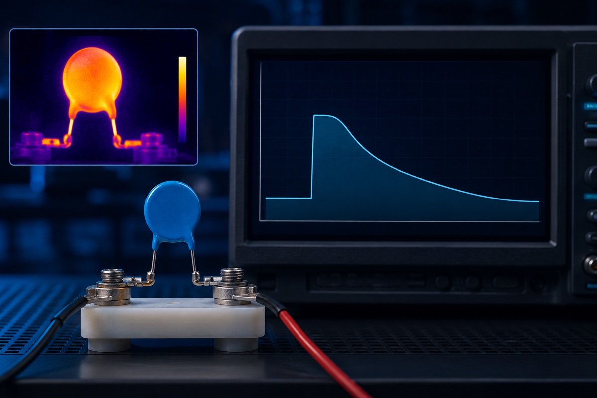
If a datasheet states 1.25 per unit for 1 second, the duration and voltage reference are part of the rating. The number is not a new maximum continuous operating voltage (MCOV). Before using any temporary-overvoltage (TOV) point, identify the exact product, voltage basis, time, thermal and prior-duty conditions, and stated endpoint.
This distinction matters because “MOV TOV data” can appear in documents for a bare disc varistor, a thermally protected MOV, a hybrid protector, a complete low-voltage surge protective device (SPD), or a medium-voltage arrester. Those products do not share one universal curve. The goal is to learn a reading method without transferring a value from one construction or standard to another.
What a TOV point actually authorizes
A TOV point is a conditional test statement: the named product was exposed to a defined voltage for a defined time and met a defined result under the document’s conditions. It does not authorize continuous operation at that voltage, a longer event, a different protection mode, or a different mounting arrangement.
MCOV belongs to normal continuous service. In low-voltage SPD documents, the continuous-voltage symbol is commonly Uc; product families may use other notation. TOV data describes abnormal, time-limited stress, and low-voltage SPD documents commonly use UT for a temporary-overvoltage characteristic. Symbols must be interpreted within the exact document, not treated as universal synonyms across every MOV-based product. For the normal-voltage side of the decision, begin with MOV MCOV selection.
Capture six fields before using a number
| Field | What to record | What goes wrong if it is omitted |
|---|---|---|
| Product scope | Exact series, part number, component or assembled-device type, and mounting | Data may be transferred from an SPD or arrester to a bare MOV |
| Voltage basis | Absolute or per-unit value; MCOV, Uc or Ur reference; RMS, peak or DC; connection points | The same plotted number can represent a different physical voltage |
| Duration | Line cycles, milliseconds, seconds, minutes, or hours | A temporary rating is misreported as continuous |
| Initial and thermal state | Ambient, cooling, enclosure, prior surges, bias, aging and allowed recovery | The tested heat balance no longer matches the application |
| Source and sequence | Frequency, source impedance, available fault current, repetitions, interval and current limiting | Conduction, disconnection and fault energy may change |
| Endpoint | Withstand, thermal stability, parameter limits, disconnector operation or safe failure | A non-hazardous failure can be mistaken for retained protection |
IEC 61643-331 is an MOV component test specification and its public scope notes that characteristics apply to the test mountings it describes. IEC 61643-11 addresses complete SPDs on AC low-voltage systems and calls out system and fault conditions such as expected short-circuit current and TOV stress. The distinction reinforces a practical rule: assembly evidence is not automatically component evidence, and component evidence is not a complete SPD approval.
Curve, table, or point rating: use the same reading sequence
- Read the caption first. Confirm the exact product and whether the curve represents capability, damage, test points, or another boundary.
- Decode the vertical axis. Check whether it is absolute voltage or per unit of MCOV, Uc, or rated voltage Ur. Confirm RMS, peak, or DC and the terminals being measured.
- Inspect the time scale. TOV plots often use a logarithmic axis, so 0.1 s, 1 s, 10 s, and 100 s may be equally spaced visually.
- Use the legend to find the allowed side. Do not assume that “below the curve” is acceptable; the plot may show a withstand boundary, damage boundary, or discrete observations.
- Attach every note. Ambient temperature, no-prior-duty or prior-duty state, repetition, cooling, and mounting can change which curve applies.
- Read the outcome. Withstand, recovery, allowed drift, thermal opening, and safe failure lead to different system decisions.
Suppose a purely illustrative curve shows 1.25 per unit at 1 s and 1.10 per unit at 100 s. Those are two voltage-duration combinations, not a continuous rating. A point at 10 s should not be estimated with ordinary linear interpolation unless the manufacturer defines that method. When a requirement falls between published values or near a boundary, obtain tabulated data or an application review and apply engineering margin.
Why MOV, SPD, and arrester curves cannot be exchanged
Eaton publishes per-unit TOV curves for specific medium-voltage MOV arresters, with conditions such as ambient temperature and prior duty. The plots are useful examples of correctly labeled references and logarithmic time. They are not ratings for a board-mounted radial MOV: the voltage class, construction, cooling, installation, and governing evidence are different.
A DEHN low-voltage SPD datasheet uses another valid format: discrete UT voltage-duration entries followed by an endpoint such as “withstand.” That is evidence for the named assembled SPD, including its internal switching or disconnection architecture. It cannot be reduced to a bare MOV capability. Conversely, a disc MOV’s component tests do not establish an SPD’s short-circuit, enclosure, disconnector, and protection-mode behavior.
TOV is not the same dataset as surge current or energy
Impulse ratings commonly use microsecond waveforms such as 8/20 µs current, while a voltage swell or TOV can last for line cycles, seconds, or minutes. Littelfuse C-III data, for example, separately identifies steady-state applied voltage, 8/20 µs peak current, and 2 ms energy. The table does not turn one field into another, and a 2 ms joule rating cannot be used to invent a missing TOV envelope.
Varistor voltage and clamping voltage are separate again. V1mA is a reference measured at the specified 1 mA DC test current for product families that define it that way. Clamping voltage is measured while a stated impulse current and waveform flow. Neither value states how long a power-frequency abnormal voltage can remain applied.
Why a discrete MOV’s TOV capability is often thermally limited
MOV current rises nonlinearly with applied voltage. Once an abnormal power-frequency voltage produces meaningful conduction, instantaneous dissipation follows p(t) = v(t) × i(t), and the accumulated heat depends on the power history and thermal path. Rising temperature can increase leakage and move the balance toward further heating. Bourns’ voltage-swell discussion illustrates this mechanism for conventional MOVs exposed to an extended abnormal voltage.
For a complete SPD, thermal behavior is only part of the review. Insulation, protection mode, available short-circuit current, enclosure behavior, internal or external disconnection, and the state after the event also matter. MOV temperature derating provides the component-side starting point, but it is not a substitute for system fault analysis.
Higher MCOV creates a second tradeoff
Choosing a higher-MCOV MOV may reduce normal bias stress and reduce conduction during some abnormal voltages. Within a product family, however, a higher continuous rating commonly moves varistor and clamping levels upward. The protected circuit may then experience a higher residual voltage during a surge.
The useful decision is therefore not “maximize TOV headroom.” It is to fit the normal voltage, credible TOV envelope, surge current, clamping window, downstream withstand, temperature, and disconnect strategy at the same time. A change made for one condition must be rechecked against the others.
The endpoint determines what the equipment must do next
Withstand normally means the product continues to satisfy specified post-test requirements. A thermal disconnector opening is an intentional state change. Safe failure can mean the tested assembly reaches a defined non-hazardous outcome without remaining functional as a surge protector. Read the actual acceptance measurements: varistor-voltage shift, leakage, insulation, continuity, temperature trend, enclosure condition, and thermal stability.
A load can remain powered after a protection branch opens, which makes status indication and service policy important. A line fuse opening—or simply observing no flame—does not prove that surge protection remains available. See why a line fuse does not replace an MOV thermal disconnector.
Translate the system fault into a qualification plan
- Document nominal and maximum normal voltage, tolerance, regulation, ripple, frequency, grounding, and operating temperature.
- Describe each credible abnormal state by terminals, voltage definition, duration, source impedance, and available current.
- Select the exact component or SPD configuration before collecting TOV evidence; avoid family-level assumptions.
- Convert per-unit data only with the reference named on that plot. Keep RMS, peak, DC, line, phase, Uc, and Ur distinct.
- Overlay the application event and the documented capability, then add margin for tolerance, temperature, aging, repeat events, and measurement uncertainty.
- Recheck surge clamping, interconnect inductance, thermal disconnection, overcurrent protection, and the post-event protection state.
- Validate the complete assembly at worst case with qualified personnel, isolation, current limiting, remote operation, temperature monitoring, containment, and explicit stop criteria.
If the exact product document provides no TOV curve or point rating, request product- and mounting-specific evidence from the manufacturer or include the event in a controlled system test. Do not back-calculate TOV capability from V1mA, clamping voltage, one-shot surge current, or joule rating.
Review checklist for a supplier comparison
- Are both candidates the same device class and protection architecture?
- Do the axes use the same reference voltage and RMS/peak/DC convention?
- Are ambient, prior duty, mounting, repetitions, and recovery conditions aligned?
- Does “pass” mean continued operation, allowed parameter change, disconnection, or safe failure?
- Has a higher-MCOV option been checked against downstream clamping margin?
- Are the exact order code, current document revision, lifecycle status, and system test plan recorded?
Frequently asked questions
Is TOV the same as a voltage swell?
The terms overlap in many power-quality discussions, but definitions and duration classes depend on the document and application. Treat the label as a prompt to capture voltage, duration, source, and protection mode—not as permission to reuse a test level from another standard.
What if the datasheet gives only TOV points instead of a curve?
Keep each voltage-duration-endpoint entry as a discrete record. Do not draw an interpolation or extrapolation unless the manufacturer defines one. If the system condition lies between points, request clarification or test the exact assembly with margin.
Is every point below a descending curve acceptable?
No direction can be assumed from shape alone. Use the legend, notes, and endpoint definition to identify the permitted region, then match product, reference voltage, ambient, prior duty, mounting, source, and repetitions. A component plot is not a complete product safety approval.
Does an integrated thermal disconnector make any TOV safe?
No. The disconnector has defined voltage, current, temperature, mounting, and interruption limits. It may create a safe state for specified abnormalities, but available fault current, enclosure behavior, loss of protection, and equipment compliance remain separate checks.
Takeaway
The portable lesson is a record format, not a curve value: exact product, voltage reference, duration, thermal and prior-duty state, source and sequence, and endpoint. Treat MCOV as the continuous-service boundary and TOV as conditional abnormal-event evidence. Then coordinate both with surge clamping and the protection state after the event. For the broader parameter map, continue with MOV key parameters.
References
- IEC 61051-2:2021, Sectional specification for surge suppression varistors
- IEC 61643-331:2020, Performance requirements and test methods for MOVs
- IEC 61643-11:2025, Requirements and test methods for AC low-voltage SPDs
- Littelfuse, C-III Series Radial Leaded Varistors Datasheet
- Bourns, MOV and IsoMOV performance during extended voltage swell events
- Eaton, VariSTAR AZU medium-voltage MOV arrester TOV curve example
- DEHN, low-voltage SPD Uc and TOV point-rating example












