

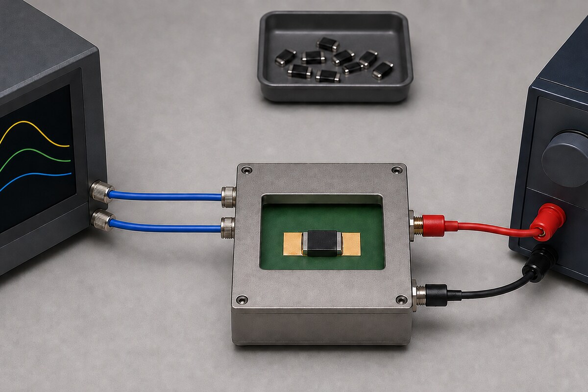
A ferrite bead can remain below its catalog current rating and still provide less useful impedance than the filter design expects. That is not a contradiction. The current rating usually answers a thermal question under stated temperature-rise and derating conditions. Effective impedance answers an electrical question at a particular frequency, DC load current, temperature, and network operating point.
Treat bead selection as a two-gate decision. First, verify DCR heating, ambient temperature, board cooling, and derating. Then verify that the exact orderable part retains the required Z, R, X, and system attenuation under bias. Passing the thermal gate does not pass the filtering gate. For broader context on component roles, see the electronic components overview.
Start with Z, R, and X—not with saturation shorthand
Ferrite-bead impedance is complex: Z = R + jX, and |Z| = √(R² + X²). The real component R contains DCR plus frequency-dependent AC losses such as core loss; it is therefore not interchangeable with a datasheet’s single DCR value. X reflects the reactive response associated with effective inductance and parasitics. Analog Devices separates DCR, bead inductance, parasitic capacitance, and AC core-loss resistance in a simplified model, then shows why the response moves through mainly inductive, resistive, and capacitive regions with frequency (S7).
A catalog value such as 600 ohm at 100 MHz is therefore one impedance magnitude at one condition. It does not define behavior at 1 MHz, 10 MHz, or across the noise spectrum, and it does not make the component a 600 ohm resistor. A useful review keeps the |Z|, R, and X/XL curves distinct.
What the DC magnetizing field changes
Load current establishes a DC magnetizing field and moves the ferrite operating point toward saturation. As incremental permeability falls, effective inductance falls; in an inductive region, XL = 2πfL falls with it. Murata describes high-current magnetic saturation reducing bead impedance and says the effect in its example recovers when current is reduced, while warning that performance can still be lost during a current pulse (S1). That statement is not a waiver of thermal, damage, aging, or reliability limits.
The full response is not a zero-bias curve multiplied by one universal factor. Würth Elektronik ANP045b uses part-specific models in which inductance and damping resistance change while parasitic capacitance is treated as approximately constant, moving the impedance peak and resonance shape (S3). These shape statements remain tied to the application note, its model, material, frequency, and bias. They do not prove that R always falls or that parasitic capacitance never changes. This article explicitly excludes ANP045b’s internally inconsistent 8 GHz sentence, which switches between order codes 742861160 and 742841160.
Rated current is commonly a temperature-rise boundary
Manufacturer current definitions often attach to specified temperature rise. Murata’s BLE32PN300 example associates a 10 A rating with ΔT ≤ 40 °C, while listing impedance at 100 MHz, DCR, rated current, and an operating-temperature range including self-heating as separate fields (S2). That supports the definition for this page example; it does not establish one universal threshold for every manufacturer or family.
Magnetic bias and heating are different mechanisms that can interact. The bias field can alter incremental response immediately. I²R loss raises temperature over time, and temperature can further change magnetic behavior. A validation matrix therefore needs current and temperature axes. An impedance drop alone does not prove overheating, while an acceptable steady-state temperature rise does not prove sufficient EMI attenuation.
A controlled comparison of two 600-ohm 0603 beads
Würth’s 742861160 and 742863160 make a useful bounded comparison because both exact order codes appear in the application note and have individual datasheets. The table preserves package, revision, frequency, bias, temperature-rise, and typical-versus-limit identity. No impedance point has been digitized from a graph.
| Field | 742861160 | 742863160 |
|---|---|---|
| Package and datasheet | 0603, Rev 005.000, 2020-03-03 | 0603, Rev 004.000, 2020-03-03 |
| Impedance at 100 MHz | 600 ohm ±25% | 600 ohm ±25% |
| Typical maximum impedance | 900 ohm at 350 MHz | 950 ohm at 600 MHz |
| Rated current at 20 K rise | 200 mA max | 400 mA max |
| Rated current at 40 K rise | 500 mA max | 500 mA max |
| DCR at 20 °C | 0.27 ohm typ. / 0.9 ohm max | 0.22 ohm typ. / 0.35 ohm max |
| Published bias traces | 100/200/300/500 mA | 100/250/400/500 mA |
The 742861160 datasheet (S4) and 742863160 datasheet (S5) support one narrow conclusion: equal package and equal zero-bias impedance at one frequency—even the same 500 mA at a 40 K rise—do not establish equal DC-bias response or equal broadband behavior. The comparison does not identify a universally superior material and must not be transferred to other series.
Give every curve an identity card
Before reusing a graph or model, capture the following fields together:
- manufacturer, full orderable part number, family, and package;
- datasheet revision/date or model-tool version;
- plotted quantity: |Z|, R, X/XL, L, S21, or insertion loss;
- frequency point or sweep covering the actual noise band;
- DC bias, including steady-state, peak, pulse duration, and duty cycle;
- ambient, self-heating, DCR condition, and applicable derating;
- evidence class: typical, simulation, measured example, tolerance, or guaranteed limit;
- fixture, calibration, board, source, load, and capacitor conditions when stated.
If the datasheet supplies only impedance at 100 MHz and no bias curve, request part-specific data or measure under bias. Do not estimate retained impedance from rated current. The electronic component abbreviations guide can help with terminology, while arrays and feedthrough filters provides an adjacent filtering-structure comparison. Neither overview replaces object-level evidence.
Where the popular ADI examples stop
ADI AN-1368 provides valuable measured examples of biased beads and bead-capacitor networks. Its percentages of rated current, impedance changes, cutoff shifts, and dB results stay attached to the named examples and test networks; none is a universal safety factor. The article labels a TDK sample with the shortened code MPZ1608S101A. TDK’s current product page uses the full code MPZ1608S101ATAH0 (S8). Without a revision mapping, the two are not automatically the same test object, and the ADI curve cannot become a current TDK specification.
ADI also discusses Würth 742792510. Its Rev 006.000 datasheet identifies an 1812 bead with 5 A at a 20 K rise and 6 A at a 40 K rise (S6). Those values confirm thermal-rating identity only; they do not convert ADI’s measured bias response into a Würth guaranteed limit.
Validate the bead in the actual power network
- Measure or define the noise frequencies to suppress. Do not assume the relevant point is 100 MHz.
- Define nominal and maximum steady-state current, startup and load-step transients, ambient temperature, and duration.
- Obtain bias-dependent Z/R/X data for the full candidate part number across the target band. Record uncertainty when only typical curves exist.
- Place the biased model in the real network, including source impedance, load, capacitors, ESR/ESL, and layout parasitics. A bead-capacitor combination can introduce resonance.
- On the target PCB, compare spectra, ripple, ringing, insertion loss or emissions across load and temperature, and record component temperature.
- Accept against the system’s EMC or functional limit, not merely the component current rating.
Frequently asked questions
Can ferrite-bead impedance fall below the rated current?
Yes. Rated current is commonly tied to a thermal condition. Impedance retention needs separate data for the exact part, frequency, DC bias, and temperature.
Is ferrite-bead saturation permanent?
Murata describes recovery when current is reduced for the magnetic-saturation effect it discusses, while noting loss of performance during the pulse. That does not guarantee freedom from overheating, damage, hysteresis, or long-term reliability effects in every product.
Is a 600-ohm ferrite bead a 600-ohm resistor?
No. It is an impedance magnitude at a stated frequency and condition. The R/X mix changes with frequency and bias; DCR is a separate parameter.
Does choosing twice the load current solve DC bias?
It may screen candidates, but it cannot guarantee target-band impedance, network attenuation, or temperature rise. Part-specific curves and board validation remain necessary.
Why can two 600-ohm, 0603 beads behave differently?
One catalog point does not define material, DCR, loss peak, broadband response, or bias behavior. Compare complete order codes under complete operating conditions.
Use two acceptance gates
Do not end ferrite-bead selection at the 100 MHz impedance and maximum-current columns. Verify the thermal boundary, independently verify biased Z/R/X across the real noise band, and then validate the complete network. Every numerical claim should retain full part number, package, frequency, bias, temperature, revision, and typical-versus-limit status. If those fields are missing, the result is a candidate—not a design guarantee.
First-party references
- S1: Murata, precautions for using chip ferrite beads
- S2: Murata, Monolithic Type Ferrite Bead example
- S3: Würth Elektronik, ANP045b
- S4: Würth Elektronik 742861160 datasheet
- S5: Würth Elektronik 742863160 datasheet
- S6: Würth Elektronik 742792510 datasheet
- S7: Analog Devices, Ferrite Beads Demystified / AN-1368
- S8: TDK, MPZ1608S101ATAH0 current product page












