
UBAEC | Electronic Components & Application Insights
  • Components
  • Applications
  • Wiki
    • Submit a Technical Question
  • Technical Topics
  • Industry News
No Result
View All Result
  • MOV
  • MLV Knowledge Map
UBAEC | Electronic Components & Application Insights
  • Components
  • Applications
  • Wiki
    • Submit a Technical Question
  • Technical Topics
  • Industry News
No Result
View All Result
UBAEC | Electronic Components & Application Insights

MOV Protection for AC-DC Power Supplies: Placement, Fusing and Coordination

Viki by Viki
2026-08-10
in Application Notes
A A
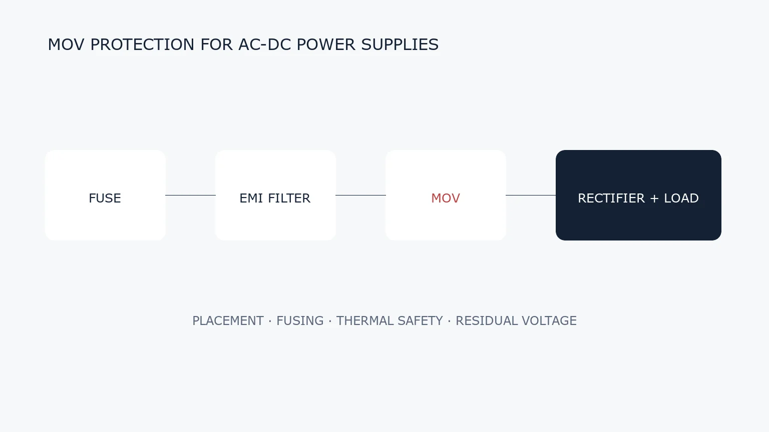
AC-DC power supply input protection chain with fuse, EMI filter, MOV and rectifier
Share on FacebookShare on Twitter

An MOV at the input of an AC-DC power supply can limit short-duration overvoltage, but its effectiveness depends on placement, wiring inductance, fuse coordination, thermal protection and the actual surge test. It should be designed as part of the complete input network rather than selected from mains voltage alone.
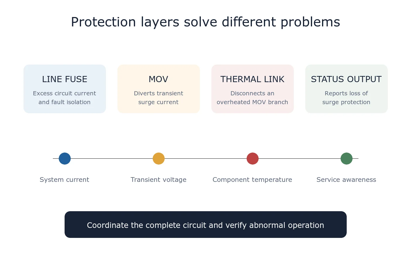
Diagram comparing an upstream line fuse, MOV branch, thermal disconnect and status-monitor output
The fuse, MOV and thermal disconnect solve different failure conditions.

Typical Input Protection Chain

A common sequence is connector, fuse, inrush-current limiter, EMI filter, MOV and rectifier, but the exact order depends on safety, EMC and surge objectives. The MOV should be placed across the conductors it protects with a short, low-inductance current loop. Long PCB traces increase residual voltage during a fast surge.

Select Maximum Continuous Voltage First

Start with the highest continuous line voltage, not the nominal voltage. Include mains tolerance and the system’s credible abnormal conditions. Check the manufacturer’s maximum continuous AC voltage (MCOV) separately from V1mA and clamping voltage.

Translate the Equipment Test into MOV Stress

For IEC 61000-4-5 testing, record the generator level, coupling mode, source impedance, polarity and pulse sequence. Estimate the current through the MOV, then verify the residual voltage at the protected node. The open-circuit test level is not an MOV voltage rating.

Coordinate the Fuse and Thermal Protection

The line fuse protects against excessive circuit current. A degrading MOV can become hot while drawing less than the fuse opening current. Mains-connected designs may therefore require a thermally coupled disconnect or a thermally protected MOV, depending on the safety analysis and applicable standard.

Check the EMI Filter Interaction

The common-mode choke and X/Y capacitors change surge propagation. Decide whether the MOV sits before or after parts of the filter by evaluating insulation stress, conducted emissions and the intended current path. Do not place the MOV where a surge return path bypasses the protective conductor strategy.

Design Checklist

  • Maximum normal AC voltage and temporary overvoltage.
  • Line-to-line and line-to-ground coupling paths.
  • Peak MOV current, waveform, pulse count and interval.
  • Maximum residual voltage versus rectifier and bulk-capacitor withstand.
  • Fuse clearing behavior and available fault current.
  • Thermal disconnect, spacing and flame requirements.
  • PCB loop length and distance from heat-sensitive parts.
  • Post-test leakage, V1mA shift and functional checks.

Common Mistakes

Typical errors include using V1mA as MCOV, selecting only by joule rating, assuming a line fuse protects every MOV thermal failure, and testing only one polarity or coupling path. Another mistake is lowering the MOV voltage to improve clamping without checking continuous leakage and TOV behavior.

Related Guides

  • IEC 61000-4-5 Surge Test Explained
  • MOV Failure Modes and Thermal Protection
  • How to Select an MOV

Reference

  • Littelfuse — Designing with Thermally Protected MOVs in SPD and AC-Line Applications

For a private review, send the input-voltage range, surge requirement, schematic and fuse data through Ask UBAEC.


Next Post
LED driver surge protection architecture with AC input MOV, driver stage and LED load

MOV Surge Protection for LED Drivers and Outdoor Lighting

Automotive Load Dump Protection: Selecting MOV, TVS and MLV Devices

  • Trending
  • Comments
  • Latest
Blue radial metal-oxide varistors used for transient overvoltage protection

What Is a Varistor? MOV Basics and Key Parameters

2026-09-07
Populated electronic circuit board on a laboratory test bench

What Are Electronic Components? Common Types, Functions and Selection Basics

2026-09-07
Conceptual MLV operating regions from normal leakage through transient conduction to post-pulse recovery

How Multilayer Varistors Work

2026-09-07
IEC 61000-4-5 combination-wave surge test chain from generator through coupling network to equipment under test

IEC 61000-4-5 Surge Test Explained: Waveforms, Coupling and Interpretation

2026-08-10
Populated electronic circuit board on a laboratory test bench

What Are Electronic Components? Common Types, Functions and Selection Basics

1
Oscilloscope probes measuring surge residual voltage between the protected node and local return after an MOV

Why Do MOV Leads and PCB Traces Increase Residual Voltage?

1
Blue radial metal-oxide varistors used for transient overvoltage protection

What Is a Varistor? MOV Basics and Key Parameters

0
Multilayer chip varistors and molded surface-mount MOV packages used for circuit protection

What Is an SMD MOV? Types, Parameters and Applications

0
GDT devices with a surge generator and oscilloscope in a circuit-protection test setup

Why Can a GDT Keep Conducting After a Surge?

2026-09-16
Single two-terminal MLCC in a measurement fixture with a completed thermal-history backdrop and a conceptual slow downward time trend

MLCC Aging and De-Aging: Capacitance After Reflow and Referee Time

2026-09-15
Disc MOV on a test fixture with a thermal image and a time-voltage withstand curve

How to Read MOV TOV Data: Temporary Withstand Is Not MCOV

2026-09-14
Three-lead thermally protected MOV connected to a status LED and optocoupler test board

How Should the Third Lead of a Thermally Protected MOV Be Wired?

2026-09-13

Need help selecting a component?

Share the operating voltage, package, surge or ESD conditions. We will help you identify the parameters that matter.

Submit a technical question

About UBAEC

UBAEC provides electronic component information, circuit protection knowledge, application guidance, and inquiry support for engineers and sourcing teams.

Categories

  • Application Notes
  • Automotive
  • Basics
  • Consumer Electronics
  • Cross Reference
  • Downloads
  • Industrial Control
  • Industry Insights
  • LED Lighting
  • Manufacturers
  • MLV
  • Parameters
  • Protection Circuits
  • Selection Guide
  • Standards
  • Technical Q&A
  • Telecommunications

Recent Post

  • Why Can a GDT Keep Conducting After a Surge?
  • MLCC Aging and De-Aging: Capacitance After Reflow and Referee Time
  • About
  • Contact
  • Privacy Policy
  • 中文

© 2026 UBAEC — Electronic Components & Application Insights. All rights reserved.

No Result
View All Result
  • Home
  • Component Center
  • Applications
  • Technical Wiki
  • News
  • Contact

© 2026 UBAEC — Electronic Components & Application Insights. All rights reserved.








