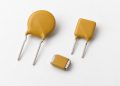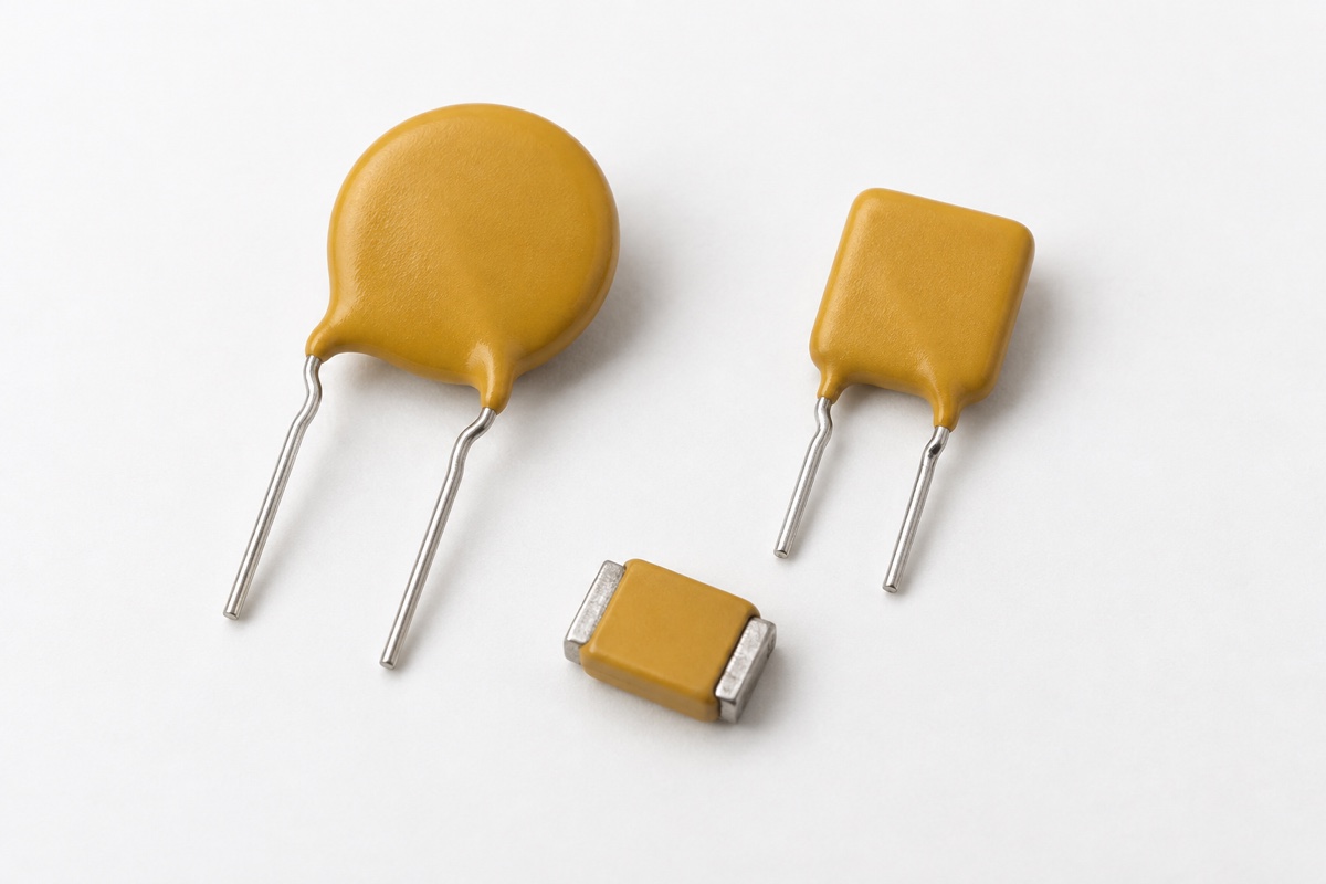
A polymeric positive temperature coefficient device (PPTC) is called resettable, but that word describes a return to a conductive state—not an instant return to the resistance measured when the part left the factory. After an overcurrent event, the polymer structure must cool and rebuild lower-resistance conductive paths. The load may restart while the device still has more resistance, voltage drop, and self-heating than it had before the trip.
This is why PPTC datasheets separate initial resistance from post-trip resistance. A design based only on Rmin or Rmax can pass a first-start calculation and still suffer a brownout after a fault. The useful question is not merely “does it reset?” but “what resistance is allowed after the specified trip, cooling interval, ambient temperature, and power-removal condition?”
Functional reset and resistance recovery are different
A PPTC contains conductive particles distributed through a polymer matrix. Fault current creates I²R heating; once the material reaches its transition region, its resistance rises sharply and limits current. Removing the fault and the electrical power allows the device to cool so that conductive paths can reform. Because this is a thermal and material process, it does not behave like a digital latch with one fixed reset delay.
Functional reset occurs when resistance has fallen enough for the circuit to operate again. Exact resistance recovery can continue after that point. Ambient temperature, package size, PCB copper, airflow, trip energy, the completeness of power removal, and the new load current all affect the trajectory. Reapplying power too early can generate enough heat to slow or stop further recovery.
Initial resistance and R1max answer different questions
Initial Rmin and Rmax normally describe the as-supplied resistance range at a stated temperature. They support the first calculation of normal voltage drop and dissipation, but they are not a promise that every part will remain inside that window after soldering, tripping, and thermal cycling. Surface-mount families may also specify a separate post-reflow limit, which must not be confused with a post-trip limit.
Bourns defines post-trip resistance R1max as the maximum resistance one hour after a device has tripped and power has been removed. The one-hour interval and removal of power are part of the definition, not optional context. A Littelfuse PolySwitch product specification likewise lists initial resistance, one-hour post-trip resistance after a standard trip, and the applicable test temperature as separate entries.
R1max is not a reset-time curve
R1max is a limit at a defined measurement point. It does not show the full resistance-versus-time path from the moment power is removed. It therefore cannot tell a designer what resistance to expect after 10 seconds, two minutes, or twenty minutes, and it is not automatically the minimum safe restart delay for a particular product.
If the equipment must recover within seconds, obtain a recovery curve for the exact part or measure the resistance sequence under controlled conditions. Preserve the trip current, duration, ambient temperature, mounting, and cooling boundary because changing any of them changes the stored heat. A single room-temperature reading taken long after the event cannot validate fast automatic restart.
A standard post-trip limit is not an unlimited lifetime guarantee
Trip conditions, maximum voltage, maximum fault current, trip-cycle life, and trip endurance are separate datasheet concepts. Passing a one-hour post-trip resistance limit after a standard event does not mean the same resistance is guaranteed after an arbitrary electrical overstress, any number of cycles, or prolonged high-temperature exposure. The exact product specification has priority over a generic PPTC explanation.
The distinction also matters for qualification. Agency recognition, a manufacturer endurance test, and acceptable system voltage drop are not interchangeable proofs. A finished product must still demonstrate that its selected device, fault source, enclosure, wiring, and reset policy behave safely across the intended life and environmental range.
Why residual resistance matters in the circuit
For a PPTC in series with a supply, the approximate normal-path voltage drop is Vdrop=I×R, while device dissipation is P=I²×R. If post-trip resistance is above the initial value, a low-voltage rail can see extra droop during restart. That may cause a processor to brown out repeatedly, prevent a motor from accelerating, reduce available battery power, or increase charging time.
The additional dissipation also feeds back into recovery. A load that draws a large startup pulse can reheat the PPTC before it has cooled fully. Evaluate the worst permitted post-trip resistance together with minimum input voltage, supply current limit, cable and connector resistance, and the load’s startup waveform rather than treating the PPTC as an ideal switch.
Partial power removal can hold the device in an intermediate state
A tripped PPTC still passes a limited current, and that current can provide the heat needed to sustain the high-resistance state. Clearing the downstream short while leaving a bias or retry current is not necessarily equivalent to the datasheet condition of removing power. The device can settle at an intermediate temperature and resistance instead of following the expected one-hour recovery condition.
An automatic-reset product should define how the fault path is isolated, how long power is removed, whether a small diagnostic current remains, and what happens after a failed retry. Unattended equipment may need retry limits or a latched alarm because repeated hot restarts create thermal cycling even when each event appears to recover eventually.
Keep post-reflow and post-trip measurements separate
Reflow soldering can shift the resistance of a surface-mount PPTC, so some manufacturers publish a post-reflow resistance limit. That value and post-trip R1max may use similar notation, but they represent different conditioning histories. Incoming inspection, post-reflow measurement, and standard post-trip measurement should therefore be recorded as separate stages.
Use the stated measurement temperature, waiting interval, and sense current at each stage. A high test current can warm a small device and distort the result. Also distinguish resistance drift from the temporary effect of a warm part; otherwise a reading taken at an uncontrolled temperature can look like permanent damage or false recovery.
A practical reset and voltage-drop validation
- Lock the full part number, package, maximum voltage and fault current, and the specified Rmin/Rmax, post-reflow limit, and R1max.
- Trip the device with the datasheet’s defined current, duration, and ambient conditions; do not substitute a destructive overstress for the standard trip.
- Remove power and record device temperature and resistance versus time, covering both the planned restart instant and the manufacturer’s one-hour measurement point.
- Restart at minimum input voltage, maximum normal load, and worst ambient temperature; measure PPTC voltage drop, surface temperature, load voltage, and successful startup.
- Repeat the required number of fault cycles, then recheck resistance, nuisance trips, thermal stability, nearby material temperatures, and the behavior of any retry controller.
Keep this work distinct from the PPTC Ihold, Itrip, and temperature-derating check: that page addresses entry into the trip region, while this one addresses recovery after a trip. The linear versus nonlinear resistance guide explains why one fixed ohmic value cannot describe the entire process, and the electronic-component classification guide provides broader terminology.
Frequently asked questions
Does resistance above the initial maximum prove that the PPTC is damaged?
Not by itself. Compare the reading with the exact part’s post-trip limit using the specified temperature, power-off interval, and measurement method. Escalate it as a failure if it exceeds the applicable post-trip limit, produces unacceptable system drop or heat, or shows physical damage.
Must a PPTC return to initial resistance after one hour?
No. One hour is commonly the defined measurement point for R1max, and the allowed post-trip maximum may be higher than the initial maximum. Use the target series specification rather than assuming one universal ratio.
Can R1max predict the voltage drop at every restart time?
No. It is a limit at one specified time, not a dynamic recovery curve. Fast-restart designs require resistance-versus-time data or measurements on the exact part under the real thermal and load boundary.
Conclusion
“Resettable” means that a PPTC can return to a lower-resistance conductive state after the fault and heat source are removed. It does not promise an immediate return to the as-supplied resistance range. Separate initial, post-reflow, and one-hour post-trip resistance limits; retain their temperatures and conditioning steps; then validate restart voltage drop, dissipation, and repeated-fault behavior using the worst relevant post-trip condition.
References: Bourns, Multifuse PPTC Product Guide; Bourns, PPTC glossary and resistance definitions; Littelfuse, RUEF185S PolySwitch Product Specification.