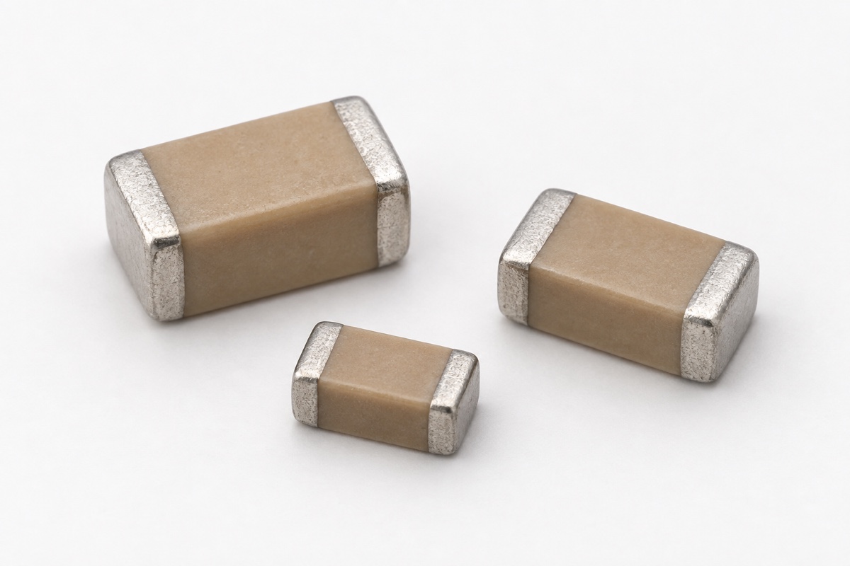
Multilayer ceramic capacitors (MLCCs) are often treated as if ripple current were irrelevant because their equivalent series resistance (ESR) is low. Low ESR is useful, but it does not eliminate heat. Alternating or pulsating voltage drives current through electrodes, terminations, contacts, and the dielectric. Conduction loss and dielectric loss then become temperature rise, with the result depending on frequency, waveform, DC bias, ambient temperature, board layout, and the exact part number.
A second shortcut is to calculate P=I²×ESR with one ESR value and declare the design safe. That relationship explains an important part of conductive loss, but ESR is frequency- and operating-point-dependent, while high-permittivity ceramics also have dielectric loss. The defensible limit is not a context-free ampere value. It is acceptable self-heating and total component temperature under the real electrical and thermal conditions.
Where MLCC ripple current comes from
Input and output capacitors in switching converters, rectifier filters, inverters, and pulsed loads all carry alternating current. For a sinusoidal approximation, IRMS=2πfCVRMS shows why frequency, capacitance, and AC voltage all matter. Converter current is rarely a single sine wave, however. Its total RMS value should be calculated from the time-domain current or from all relevant spectral components rather than inferred from one oscilloscope peak.
DC bias does not appear directly in that simple AC-current equation, but it can reduce the effective capacitance of a high-K MLCC and can alter loss behavior. Nominal capacitance, biased capacitance, harmonic content, and current therefore have to describe the same operating point. Combining zero-bias capacitance with ESR measured at an unrelated frequency produces a loss estimate that may not represent the assembled circuit.
Why a low-ESR MLCC can still heat
At a given frequency, a first-order conduction-loss estimate is PESR≈IRMS²×ESR(f,T,V). It explains why using several capacitors in parallel can reduce loss per device if current actually divides as intended. It does not remove losses in terminations, solder joints, copper, or current crowding, and it does not prove that every capacitor carries the arithmetic average current.
Dielectric loss is associated with voltage, frequency, capacitance, and dissipation factor. KYOCERA AVX’s technical paper on ceramic capacitors in switch-mode power supplies describes ESR contributions from external terminations, contacts, internal electrodes, and dielectric behavior, then connects ripple-current loss to self-heating. That framework is useful, but its examples and temperature-rise discussion are not universal ratings for every MLCC.
Frequency changes both current and loss
For the same AC voltage, ideal capacitive current rises with frequency. At the same time, a real MLCC’s ESR, impedance, and dissipation factor change with frequency. Near and above self-resonance, parasitic inductance becomes important and the device no longer behaves as a simple capacitor. A calculation based only on a 100 kHz ESR value can miss heating caused by a switching fundamental and higher harmonics at very different frequencies.
Murata’s reference temperature-rise data provides separate current-versus-temperature-rise curves at different frequencies. This is direct evidence that the same numerical RMS current does not automatically imply the same temperature rise. Those curves are tied to an exact product, DC-bias condition, mounting, and measurement method. They are screening data for that part, not substitution curves for any capacitor with the same case size or nominal capacitance.
Read the self-heating limit with its manufacturer conditions
Murata’s ceramic-capacitor FAQ states that its general ceramic capacitors do not have one allowable ripple-current specification that can be used independently of conditions. It instructs designers to confirm self-heating and surface temperature in the actual circuit. For the product groups identified in that guidance, it gives conditions such as keeping body self-heating below 20°C when measured at 25°C ambient and keeping the surface temperature, including self-heating, within the maximum operating temperature.
The 20°C figure is a manufacturer-specific condition for the product scopes described in that document. It is not a universal IEC rule and must not be assigned automatically to another maker, series, or a specialized power-ceramic technology. KYOCERA AVX discusses a different design framework, while some high-power ceramic series publish explicit RMS-current, frequency, cooling, or case-temperature conditions. A design record should preserve the source, part number, and test condition rather than copying only the temperature-rise number.
Temperature measurement can change the answer
Measure temperature rise on the final PCB with production copper area, neighboring heat sources, enclosure, and airflow. A thick thermocouple wire can conduct heat away from a small capacitor, while an attachment that covers a termination or pad can change local cooling. Infrared measurement has its own emissivity, spot-size, and reflection errors. For certain high-voltage X7R/X7T products, Murata specifically calls for a low-thermal-mass fine K-type thermocouple and for excluding radiant heat and convection effects.
Record a stable ambient baseline, then observe the capacitor body, termination area, and nearby board until thermal equilibrium. Do not introduce a fan that will not exist in production, and do not classify heat conducted from another power component as capacitor self-heating. Keep two separate limits in the report: rise above the relevant local ambient and the highest absolute surface temperature.
Parallel capacitors do not guarantee equal current
Designers often parallel MLCCs to lower effective ESR, share ripple current, and obtain sufficient biased capacitance. Current sharing still depends on trace inductance, pad location, package, effective capacitance, and the return path. A device closest to the switching loop may carry more high-frequency current. Dividing total RMS current by the number of capacitors is therefore an ideal starting point, not a verified result.
Current probes, calibrated shunt structures, electromagnetic analysis, or thermal distribution can help identify unequal stress. Compare layout variants rather than treating the component count as proof. Keep this issue separate from capacitance movement caused by thermal history; the article on MLCC aging, de-aging, and referee time explains that different mechanism.
A practical workflow from waveform to hardware
- Lock the complete ordering code, dielectric class, rated voltage, case size, and maximum operating temperature.
- Capture capacitor current at worst-case input, load, switching frequency, duty cycle, and control mode. Calculate RMS current and retain the important harmonic content.
- Use capacitance, ESR or impedance, and manufacturer temperature-rise data for the exact part at relevant frequency, temperature, and DC bias.
- Check that DC plus AC peak voltage remains within the applicable voltage limit and that biased effective capacitance still satisfies the circuit requirement.
- On the final PCB and in the final enclosure, measure temperature rise, absolute surface temperature, output ripple, and capacitor current across minimum and maximum input, light-load modes, full load, and high ambient.
- After the required duration or repeated stress, recheck capacitance, loss, insulation, and solder-joint condition. Revalidate any alternate part or layout change according to its impact.
The reasoning resembles the method used for film-capacitor dV/dt and pulse current: waveform, frequency, temperature, and mounting must remain tied to the exact series. The dielectric systems and rating methods are different, so limits cannot be transferred between the technologies. For terminology, use the electronic-component abbreviation guide rather than assuming that ESR, RMS, and MLCC describe a complete test condition.
Common questions
If an MLCC has no ripple-current rating, can ripple be ignored?
No. The absence of one universal ampere rating does not remove the thermal limit. Apply the exact manufacturer’s voltage, frequency, self-heating, maximum-temperature, and in-circuit verification guidance.
Is staying below the maximum operating temperature sufficient?
Not necessarily. The design must also meet any manufacturer self-heating limit, voltage and effective-capacitance requirements, and reliability constraints. Internal hot spots, mechanical stress, and solder-joint behavior are not fully described by one external temperature label.
Will two identical MLCCs split ripple current exactly in half?
Only if their electrical and layout impedances are sufficiently symmetrical. High-frequency parasitics, part variation, and physical position can produce unequal sharing, so the result should be checked rather than assumed.
Conclusion
MLCC ripple capability is not determined by a blanket statement that ceramic capacitors can carry high current. Start with the actual current waveform and spectrum, use part-specific impedance and thermal data at the same frequency, bias, and temperature, and then verify self-heating and total temperature in the final board, enclosure, and airflow. Low ESR is an advantage, not permission to skip thermal validation.
References: Murata, Allowable ripple current for ceramic capacitors; Murata, SimSurfing MLCC measurement conditions; KYOCERA AVX, Key Parameters for Designing Ceramic Capacitors in SMPS Circuits.