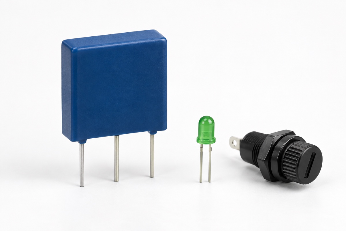
Must equipment lose power when a thermally protected metal-oxide varistor (MOV) trips? Not necessarily. In a common shunt-protection topology, the thermal disconnect opens only the overheated MOV branch while the main supply continues feeding the load. The product may therefore look fully operational even though one of its surge-protection modes is no longer available.
The design question is not simply whether the load stays on. It is what state the complete system enters after disconnection: which protection path is lost, how that condition is detected and retained, whether operation may continue, how quickly service is required, and which conditions demand an immediate shutdown. Those decisions must be made before the fault occurs.
Identify the current path that actually opens
A thermally protected MOV normally places a thermal disconnect in series with the varistor and gives the two elements a controlled thermal relationship. If sustained abnormal voltage, degradation, or another condition makes the MOV overheat, the disconnect opens to stop that branch from continuing to dissipate power. TDK’s NT-series literature describes the overheated varistor being disconnected from the power circuit, while the Littelfuse LST datasheet states explicitly that the MOV no longer protects against surge current after the thermal disconnect becomes open circuit.
An MOV connected line-to-neutral, line-to-ground, or across a DC bus is normally a shunt device, not the series switch that powers the load. Opening its branch therefore does not inherently interrupt normal load current. A lit power indicator, a running controller, and successful communication prove only that the functional power path remains. The product shuts down only if a separate interlock, relay, contactor, or control function is intentionally driven by the disconnect status.
Safe disconnection is not restored protection
The thermal mechanism addresses the risk of an overheated MOV remaining connected to an energy source. It is not an automatic repair. Once a one-shot disconnect has operated, the original surge capability does not return after cooling. If that MOV was the only element for a protection mode, that mode has been lost until the component or assembly is replaced.
This is why the LST datasheet pairs visual and remote indication with a replacement message: the protected end product needs service to continue surge protection. In a multi-mode surge protective device (SPD), line-to-neutral, line-to-ground, and neutral-to-ground paths must be assessed separately. One open branch does not prove that the remaining branches retain their original stress history, coordination, or protection rating.
A monitor lead or auxiliary contact reports state only
Monitoring interfaces differ between product families. Some thermally protected MOVs provide a third lead electrically related to the power circuit. Some SPD-oriented components provide normally open or normally closed auxiliary contacts with specified contact ratings and galvanic isolation. “Monitor output” must not be treated as a universal isolated dry contact; the exact pinout, voltage reference, isolation construction, and ratings come from the selected datasheet. See the detailed thermally protected MOV monitor-lead guide for wiring boundaries.
The sensing circuit also needs defined normal, tripped, broken-wire, and auxiliary-power-lost states. A design is not fail-safe if a detached connector or dead monitoring supply is interpreted as “protection healthy.” A normally closed loop, diagnostic bias, periodic self-test, or an independent auxiliary contact can make loss of the monitoring path produce an actionable abnormal state, although the appropriate method depends on the safety architecture.
Why the alarm often needs to latch
Disconnection may occur while the product is unattended and may coincide with a brownout or controller reset. If the alarm exists only in volatile memory, the product can reboot and present a misleading healthy display. A mechanical flag, nonvolatile event record, or independent monitoring circuit should preserve the condition together with the affected mode, operating state, time, and any available thermal evidence.
The monitoring interface must remain within its own voltage, current, and insulation ratings. Littelfuse specifies the LST auxiliary-contact ratings separately from the main MOV ratings; this distinction is a practical reminder that a signal contact cannot inherit the power branch’s capability. Current limiting, isolation, creepage and clearance, surge exposure, and accessible-circuit voltage still require a circuit-level review.
Choose continued operation or shutdown by consequence
There is no universal post-trip policy. A consumer product that can stop safely and be serviced promptly may remove load power and show a local fault. A communications, power, or industrial system that cannot tolerate abrupt shutdown may instead enter controlled degraded operation, but it should issue a clear, remotely accessible, latched alarm and enforce a defined service deadline or load restriction.
Continued operation must mean operation with a known protection loss, not a return to normal status. The risk assessment should consider the installation’s surge exposure, remaining protection layers, downstream insulation and withstand, available short-circuit current, unattended duration, maintenance access, and the consequence to people and critical functions. Component recognition or equipment certification does not make this operational decision automatically.
Do not infer the trip state from the line fuse
A line fuse responds to overcurrent according to its time-current characteristic. A thermal disconnect responds to temperature near the MOV. During a sustained abnormal voltage, branch current may be too low to operate the upstream fuse promptly yet high enough to heat a degraded MOV locally. That difference is why integrated thermal protection or closely controlled thermal coupling is used. The fuse-versus-MOV thermal-disconnect guide explains the coordination boundary.
Even if the line fuse eventually opens, that event alone does not prove that the MOV is safely isolated, that other protection modes remain healthy, or that power may simply be restored. The service procedure should inspect terminal state, insulation, residual leakage, enclosure condition, and adjacent printed-circuit-board damage, then replace every operated or compromised protection component.
Put the maintenance policy in the product requirements
- Draw every protection mode and the actual series or shunt position of each thermal disconnect; mark which nodes remain energized after operation.
- Define observable outcomes for healthy, tripped, open monitor wire, shorted monitor wire, and lost auxiliary power.
- Specify local indication, remote alarm, event latching, service deadline, and the conditions that prohibit continued operation.
- Name the replaceable component or module. Do not write “reset” when the thermal element is a one-shot disconnect.
- Verify the assembly under surge, temporary overvoltage (TOV), short-circuit, single-fault, and monitoring-wire fault conditions.
Testing should cover trip recognition at normal supply voltage, retained state after controller restart, loss of auxiliary power before a trip, open and shorted monitor wiring, and the observable condition of every other protection branch after one mode opens. A TOV test needs a defined voltage, duration, source impedance, sequence, and endpoint. It cannot be inferred from maximum continuous operating voltage (MCOV), varistor voltage, or a one-shot surge rating; see how to read MOV TOV data.
Separate component evidence from system evidence
A datasheet can establish how the selected device’s disconnect and monitor interface are intended to work. It does not establish the final enclosure temperature, the behavior of parallel branches, software response, alarm visibility, or the safety of continued operation in the target installation. Qualification therefore needs both exact component evidence and a system test that includes wiring, source impedance, protective coordination, ambient temperature, and foreseeable single faults.
Record the endpoint precisely. “Passed” could mean the load kept operating, the MOV branch disconnected without a hazardous thermal outcome, an alarm was generated, or the entire product became de-energized. Those outcomes are not interchangeable. A useful test report identifies which state occurred, what remained powered, what protection was lost, and whether any manual intervention was required.
Frequently asked questions
Does a thermally protected MOV reset after it cools?
Usually not. Many integrated thermal disconnects are one-shot mechanisms, and their product literature calls for component or module replacement. Follow the exact series datasheet and service instructions rather than treating the device as a resettable PTC or a software protection event.
Can service wait if the equipment still starts?
Not by default. Starting proves that the main power path remains, not that the intended surge mode is available. Delayed service is defensible only when the documented risk assessment, remaining protection, reliable alarm, and service deadline support controlled degraded operation.
Is a local status LED sufficient?
It may be insufficient for unattended or high-consequence equipment. The design also has to detect a failed LED, broken monitor wire, lost auxiliary supply, and controller reset without creating a false healthy indication. Latched and remote status may be necessary.
Practical conclusion
A thermally protected MOV is intended to remove an overheating protection branch, not to guarantee that the entire product loses power. The engineering result should be a complete state chain: which branch opens, whether the load remains powered, how much protection is lost, how the alarm persists, when service is mandatory, and when operation must stop. Only then does thermal disconnection become a managed safe state rather than a hidden loss of protection.
Continue with MOV temperature derating, or use the UBAEC contact page to provide the topology, operating voltage, protection modes, and fault conditions for a design review.