

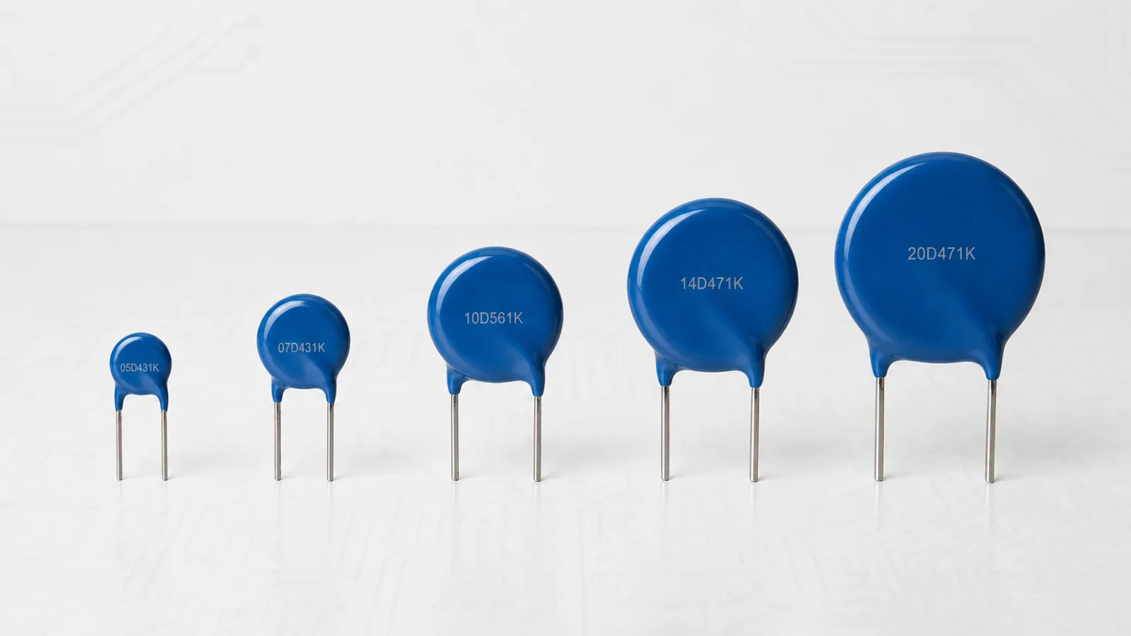
A through-hole metal-oxide varistor (TH MOV; Chinese: 插件式金属氧化物压敏电阻) is a radial-leaded voltage-dependent resistor commonly used to suppress high-energy transients in power supplies, appliances, industrial equipment and other circuits. Its familiar form is a coated ceramic disc with two wire leads.
During normal operation, the MOV draws very little current. When a transient exceeds its nonlinear region, the device conducts strongly and diverts surge current away from the protected load. It is connected in parallel with the line or component being protected.
Key point: the printed code and disc diameter are only starting points. Safe selection also requires the continuous AC/DC voltage, clamping condition, surge waveform, energy, pulse life, temperature and protection coordination.
Common Names and Chinese Terminology
- Through-hole MOV: 插件式MOV, 直插式MOV or 插件式金属氧化物压敏电阻.
- Radial leaded varistor: 径向引线压敏电阻. Both leads exit from the same side of the body.
- Disc varistor / disk varistor: 圆片式压敏电阻 or 碟片式压敏电阻, referring to the ceramic shape.
- Leaded disc MOV: 引线圆片式金属氧化物压敏电阻.
- Zinc-oxide varistor: 氧化锌压敏电阻. Most common MOV discs use a ZnO-based ceramic system.
- MOV: Metal-Oxide Varistor, 金属氧化物压敏电阻. In power-electronics discussions, MOV often informally means the radial disc type even though other packages also exist.
“TH MOV,” “radial MOV” and “disc MOV” usually refer to the same general product form, but special products may add a thermal element, monitoring lead or different encapsulation. Always confirm the lead count and internal circuit.
Construction of a Through-Hole MOV
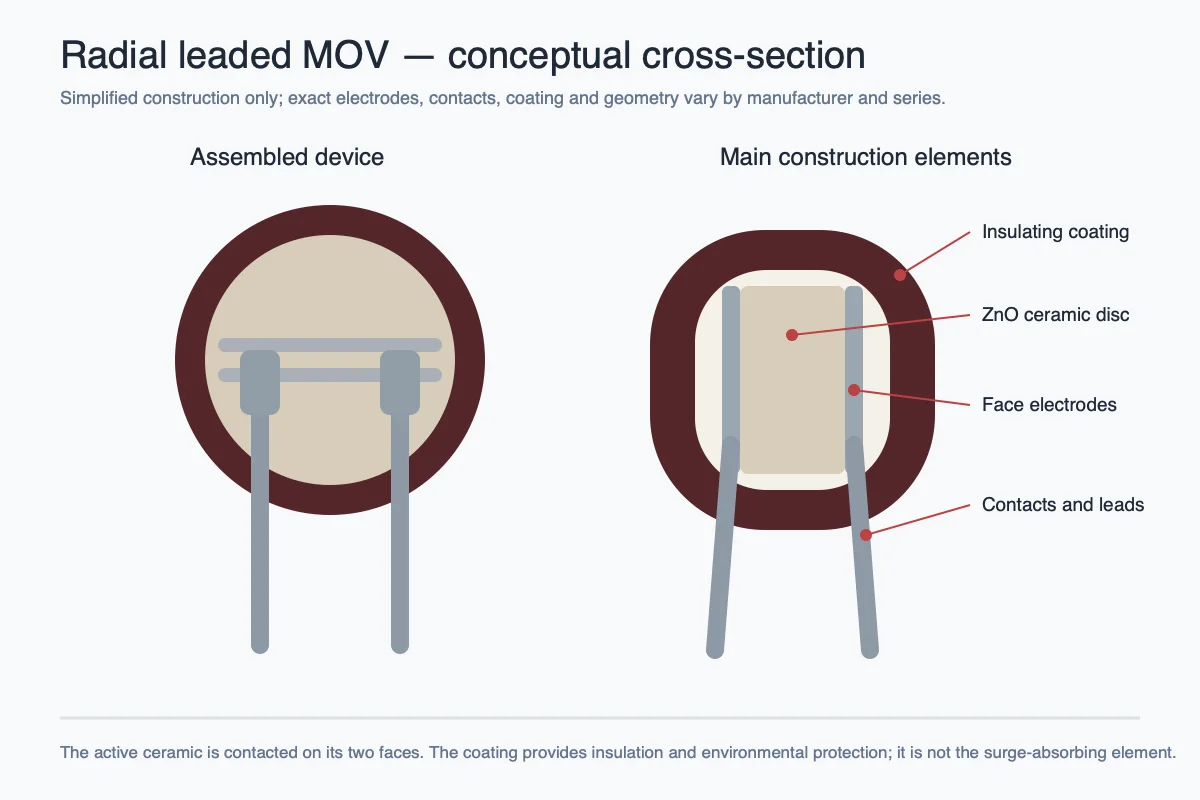
A typical radial disc MOV contains:
- A sintered zinc-oxide-based semiconducting ceramic disc
- Metal electrodes applied to both faces of the disc
- Two soldered or bonded radial leads
- An insulating epoxy or similar protective coating
- Printed identification markings
The active ceramic contains conductive ZnO grains separated by nonlinear grain boundaries. At low electric field, the boundaries block most current. At high field, many boundaries conduct, creating the steep voltage-current characteristic used for transient suppression.
The disc diameter and thickness influence performance. A larger diameter generally provides more electrode area and active volume for surge current and energy. Ceramic thickness and formulation influence the voltage grade. These relationships are useful for understanding product families but are not a substitute for the datasheet.
How a Disc MOV Clamps a Surge
The MOV is placed across the line, from line to neutral, line to protective earth, or across a DC rail depending on the system. During a surge, it changes from a high-impedance state to a low dynamic resistance and carries current through the protection path.
The voltage remaining across the circuit is the clamping voltage at that particular current. It is always higher than the normal operating voltage and normally higher than the nominal varistor voltage. Trace and lead inductance can add further overshoot, so lead length and loop area matter.
After an in-rating pulse, the MOV returns to its high-resistance state. Repeated pulses still produce cumulative stress, and a sustained overvoltage can keep the MOV conducting long enough to overheat.
Understanding Common MOV Markings
Many radial MOV part numbers combine disc size, voltage code and tolerance. For example, a marking resembling 14D471K is often interpreted as:
- 14: nominal disc diameter class, approximately 14 mm
- D: disc-type construction
- 471: nominal varistor-voltage code, commonly 47 × 101 = 470 V
- K: commonly ±10% varistor-voltage tolerance
This coding convention is widespread but not universal. Some manufacturers use different prefixes, suffixes, voltage rounding or test conditions. The code does not directly state the maximum continuous AC voltage, clamping voltage, surge current, safety approval or expected pulse life.
Similarly, “7D,” “10D,” “14D” and “20D” describe size families, not the application environment. A 14 mm device is not automatically suitable for mains, automotive or outdoor use.
The Three Voltage Values That Must Not Be Confused
Maximum continuous operating voltage
This is the highest AC RMS or DC voltage that may be applied continuously under specified conditions. It must exceed the worst-case normal voltage, including line tolerance and expected operating variation.
Varistor voltage
Varistor voltage is measured at a defined DC test current, commonly 1 mA for many radial MOVs. It is used for classification and production testing. It is not the voltage at which the MOV suddenly becomes an ideal short circuit.
Clamping voltage
Clamping voltage is the maximum voltage measured at a specified pulse current and waveform. A value stated at 10 A cannot be compared directly with one stated at 50 A. The protected circuit must withstand the worst-case residual voltage at the actual surge current.
Surge Current, Energy and Pulse Life
Peak surge current is often specified using an 8/20 μs current waveform. Energy may be specified using a 10/1000 μs waveform or another test. These ratings describe different stresses and must be read with their conditions.
A one-time maximum is not a recommended repetitive operating point. Datasheets may provide curves showing how allowable peak current falls as the number of pulses rises. Temperature can also require derating.
When comparing two MOVs, check:
- Waveform and source impedance
- One-pulse and two-pulse current ratings
- Energy rating and pulse duration
- Repetitive pulse curves
- Maximum clamping voltage at the stated current
- Ambient-temperature derating
Typical Applications
- AC mains input of switching power supplies
- LED drivers and lighting equipment
- Household appliances and white goods
- Industrial controllers, relays and motor drives
- Power adapters, chargers and inverters
- Telecommunications power interfaces
- Renewable-energy and energy-storage equipment
- Automotive power lines when the selected series is rated for the required pulses
- Suppression of inductive switching transients
The MOV protects the electrical input or power stage, not the LED chip or processor directly. For example, in an LED lamp it is typically placed in the driver input protection network.
AC Input Protection and Fuse Coordination
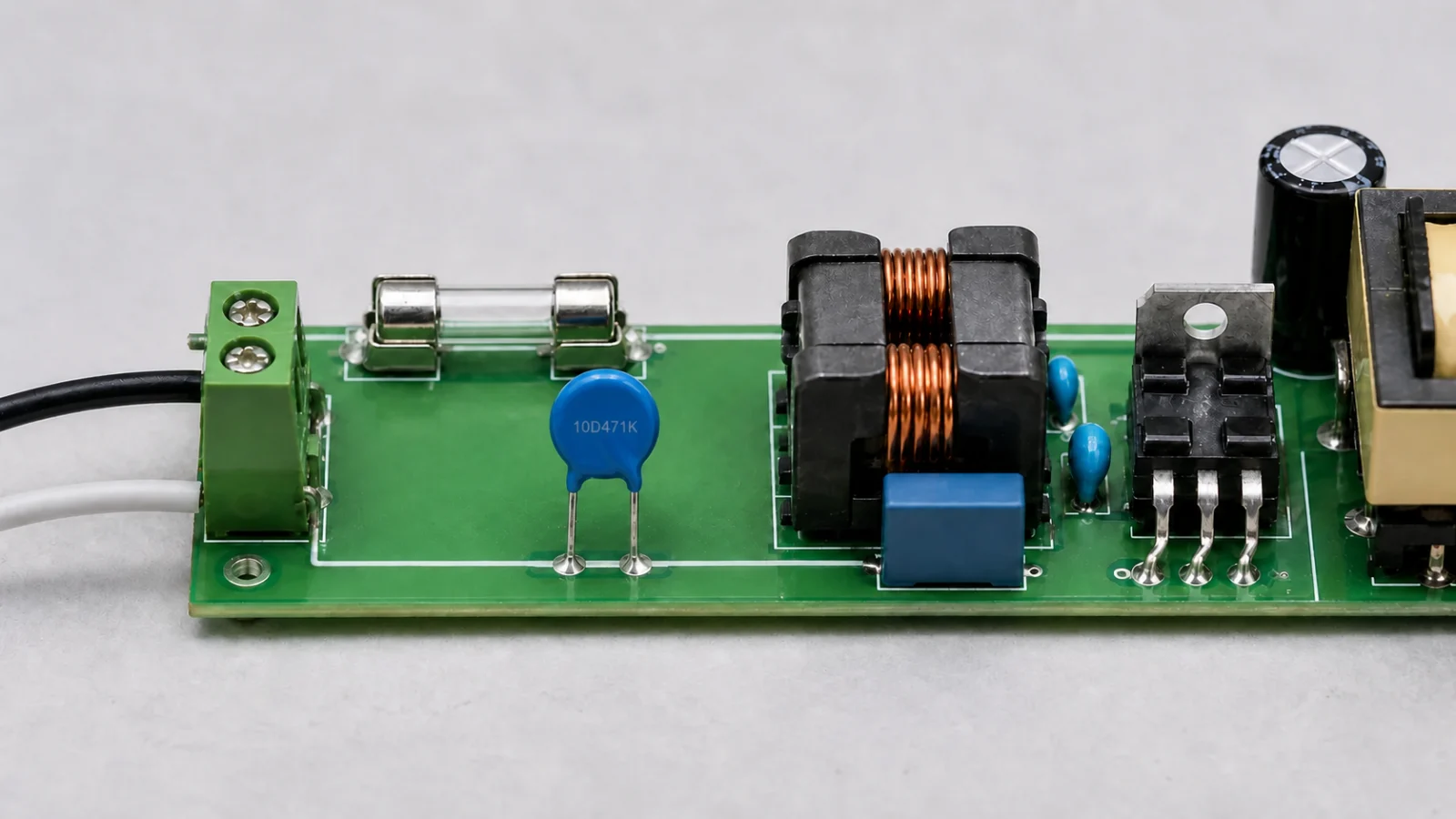
A common AC arrangement places a fuse in series with the line and an MOV across line and neutral after the fuse. The MOV handles short transient energy, while the fuse is intended to interrupt excessive fault current under appropriate conditions.
However, a standard fuse may not open quickly enough during gradual MOV overheating caused by sustained abnormal overvoltage. Depending on the safety requirement, the design may need a thermal fuse in close thermal contact, a thermally protected MOV, monitoring circuitry or another coordinated disconnection method.
Line-to-earth and neutral-to-earth protection also introduces insulation, leakage and safety-standard considerations. The complete protection network should be designed for the equipment class and applicable standard.
How to Select a Through-Hole MOV
- Determine the maximum normal AC RMS or DC rail voltage.
- Choose an MOV continuous-voltage rating above that worst-case value.
- Define the surge waveform, source impedance and expected peak current.
- Confirm that maximum clamping voltage stays below the protected circuit limit.
- Check energy and repetitive-pulse endurance with suitable margin.
- Select disc size based on verified ratings, not diameter alone.
- Check temperature, lead spacing, coating, flammability and agency approvals.
- Coordinate the MOV with fusing or thermal disconnection where required.
- Validate the system in the actual surge and abnormal-overvoltage tests.
Placement and Assembly
Keep MOV leads as short as practical to reduce inductive overshoot, but do not bend them too close to the coating. Maintain the manufacturer’s minimum lead-bend distance and spacing. Avoid mechanical force on the ceramic body during forming, insertion and depanelization.
Provide adequate creepage, clearance and thermal spacing. Do not place heat-sensitive material against a device that may become hot during a fault. In high-vibration equipment, consider mechanical support that does not stress the coating or leads.
Ageing and Failure Modes
Over time, excessive pulse stress can lower varistor voltage and increase leakage. Increased leakage generates more heat at normal voltage, which can accelerate degradation. Severe faults may lead to cracking, puncture, short circuit, open circuit, smoke or coating damage.
Important causes include:
- Continuous voltage above the rating
- Sustained temporary overvoltage
- A surge above the current or energy limit
- Repeated pulses without sufficient margin
- Operation above the specified temperature
- Incorrect fuse or thermal-disconnect coordination
- Mechanical damage to the disc or coating
Standard MOV, Thermally Protected MOV and Hybrid Protector
A standard two-lead MOV provides voltage-dependent clamping but no built-in disconnection. A thermally protected MOV adds a thermal element intended to disconnect the varistor under specified overheating conditions. Some versions include a third monitoring lead.
Hybrid products may combine an MOV with a gas-discharge or isolation function to address leakage or lifetime requirements. Their behavior and terminal arrangement differ, so they should be selected as complete devices rather than treated as ordinary MOV replacements.
Frequently Asked Questions
Does 471 mean the MOV clamps at 470 V?
No. It usually identifies a nominal varistor voltage near 470 V at a defined test current. The clamping voltage under surge current is higher.
Can a 561 MOV and a 621 MOV be exchanged?
Not without checking the circuit. The codes generally indicate different nominal varistor voltages. Compare continuous voltage, clamping level, current, energy, size and test conditions.
Does a 14D MOV always handle more surge than a 10D MOV?
Within a comparable manufacturer series and voltage grade, the larger disc often has higher surge and energy capability. Across different series or suppliers, verify the datasheets.
Can an MOV protect against every lightning surge?
No. Its protection is limited by waveform, source impedance, current, energy and pulse count. High-exposure systems may require coordinated multi-stage protection.
Is an MOV a fuse?
No. It diverts transient current but does not provide normal overcurrent disconnection. Fuse and thermal-protection functions must be designed separately.
Conclusion
A through-hole MOV is a practical, bidirectional surge suppressor with a simple radial disc form and a wide range of voltage and energy ratings. Reliable use depends on separating continuous voltage, varistor voltage and clamping voltage; matching the pulse waveform; allowing for repetitive life and temperature; and coordinating thermal and overcurrent protection.
For a broader introduction to MOV terminology, see What Is a Varistor? MOV Basics and Key Parameters. Final selection must be verified against the current manufacturer datasheet and the actual equipment tests.












