


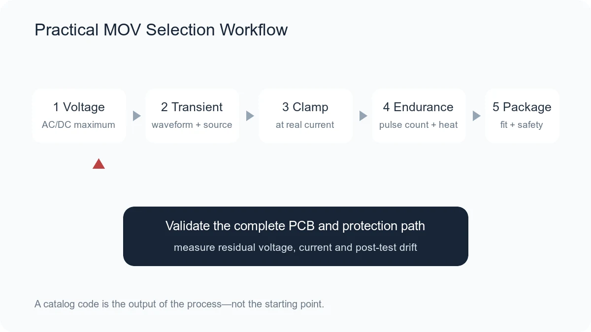
Selecting a metal-oxide varistor (MOV) is not a matter of matching one printed code. A valid choice must survive normal voltage, limit the expected transient below the load’s withstand level and tolerate the required number of pulses without unsafe heating or unacceptable parameter drift.
Selection principle: begin with the circuit and the transient, not the catalog. Define the maximum normal voltage, waveform, source impedance, peak current, pulse count and allowable residual voltage before choosing a part number.
Step 1: Define the Maximum Normal Voltage
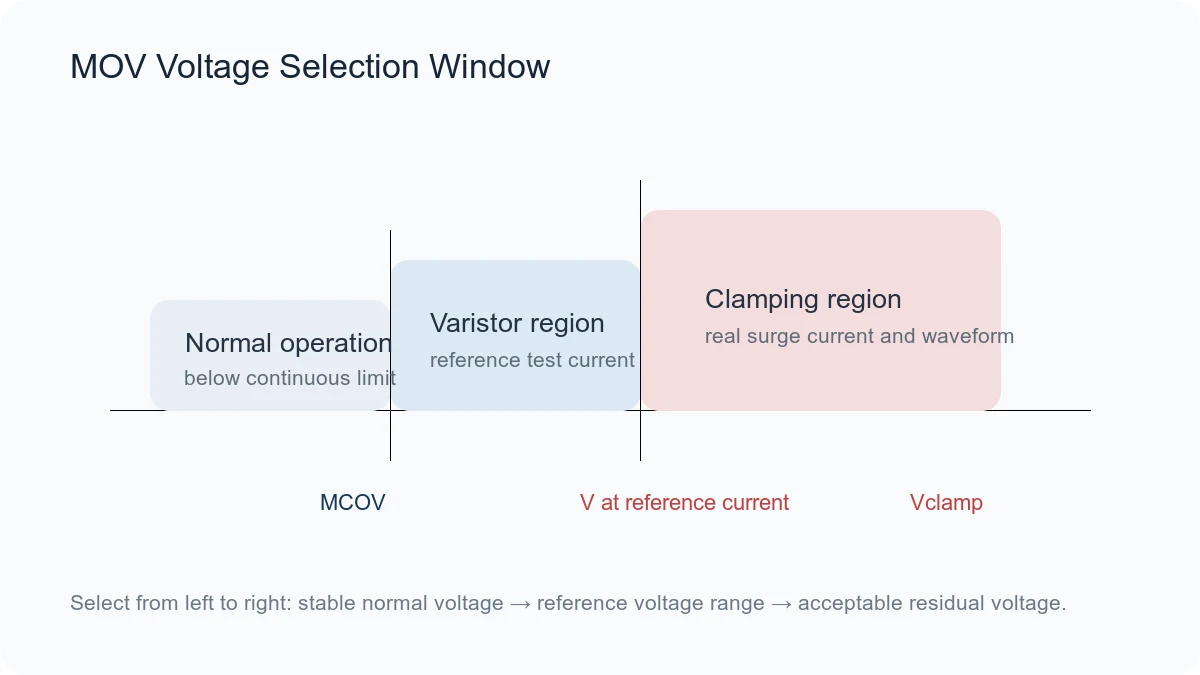
Record the highest voltage that can remain continuously across the MOV. Include supply tolerance, charging voltage, line variation, regeneration, abnormal but expected operating states and temperature. For an alternating-current (AC) line, use the correct root-mean-square (RMS) rating. For a direct-current (DC) bus, use the DC continuous rating.
The MOV’s maximum continuous operating voltage must exceed this worst-case condition with suitable design margin. Do not use nominal varistor voltage as the continuous rating. Persistent operation too close to the nonlinear region increases leakage, heating and aging.
Step 2: Identify the Transient
Different events require different evidence:
- Electrostatic discharge (ESD): very fast and short, often evaluated at system level under IEC 61000-4-2 or a customer method.
- Electrical fast transient (EFT): repetitive bursts associated with switching, commonly evaluated under IEC 61000-4-4.
- Combination-wave surge: a slower, higher-energy event associated with IEC 61000-4-5.
- Automotive pulse: may include load dump, inductive switching or manufacturer-specific pulse profiles.
- Internal switching spike: depends on inductance, current, switching speed and snubber design.
Record the voltage waveform, current waveform, source impedance, polarity, repetition and test level. A current rating under 8/20 μs does not prove performance under a longer pulse.
Step 3: Estimate the Current Through the MOV
The MOV does not experience the open-circuit surge voltage alone. Once it conducts, the source impedance and any upstream series impedance determine current. Estimate the protection current using the source model or measure it in the actual test setup.
For a simplified source, current is related to the difference between the open-circuit surge voltage and the MOV voltage divided by total source and path impedance. Because MOV voltage changes with current, a voltage-current curve or iterative calculation may be required.
Step 4: Set the Maximum Allowable Clamping Voltage
Determine the highest residual voltage that the downstream insulation, semiconductor, capacitor or interface can tolerate with margin. Then compare the MOV’s worst-case clamping voltage at the expected current and waveform.
Use maximum, not typical, curves when available. Include varistor-voltage tolerance, temperature, aging and inductive overshoot from the printed circuit board (PCB) path. A device with a suitable 1 mA varistor voltage can still clamp too high at several hundred amperes.
Step 5: Check Peak Current, Energy and Pulse Endurance
Peak surge current is usually a maximum non-repetitive rating tied to a waveform such as 8/20 μs. Energy may be tied to a different pulse. These values are not interchangeable and do not describe unlimited life.
Check single-pulse curves, repetitive-pulse curves and derating at the required temperature. If the application expects many surges, use the pulse-count data rather than the one-time maximum. When no endurance curve covers the requirement, request manufacturer confirmation or test with appropriate margin.
Step 6: Select Disc Size or Package
Larger MOV bodies often provide more active material and higher pulse capability, but size does not guarantee performance. Construction, voltage class, electrode design and manufacturer series also matter.
For a through-hole MOV, confirm disc diameter, thickness, lead spacing and coating. For an SMD MOV or multilayer varistor (MLV), confirm case size, land pattern, termination geometry, reflow profile, board-flex behavior and package creepage requirements.
Step 7: Review Leakage, Capacitance and Power
Leakage current matters in battery products, high-impedance sensing and circuits with strict standby-power limits. It increases with voltage and temperature and may increase after overstress.
Capacitance matters on communication and sensor lines. It may distort fast signals even when the voltage and surge ratings look acceptable. Rated power and continuous dissipation also matter when repetitive events or abnormal voltage can keep the MOV partially conducting.
Step 8: Apply Temperature and Reliability Derating
Review operating temperature, storage temperature, humidity, vibration, board flex and the manufacturer’s voltage, current or energy derating rules. Automotive qualification such as AEC-Q200 applies only when explicitly stated for the selected part and does not replace application-specific pulse validation.
Repeated stress can increase leakage or shift varistor voltage. Define the acceptable end-of-life behavior and include enough margin for the expected service environment.
Step 9: Coordinate Failure Protection
A surge is temporary; an abnormal overvoltage may be sustained. If the MOV conducts during a long fault, it can overheat. AC-line designs commonly coordinate the MOV with an upstream fuse, thermal disconnect, thermally protected MOV or another safe-disconnection method.
Review short-circuit and open-circuit consequences, flame and enclosure requirements, creepage, clearance and the relevant safety standard. The MOV should not be treated as a fuse.
Step 10: Verify the Complete Design
Place the MOV near the transient entry point with a short, low-inductance path. Long traces add voltage during a fast current pulse. Test the actual PCB, enclosure, wiring and upstream protection at the required standard and worst-case operating conditions.
Measure residual voltage at the protected load, current through the MOV and temperature when practical. Inspect leakage and varistor voltage after repeated testing to identify degradation.
A Practical MOV Selection Worksheet
| Input | Required information |
|---|---|
| Normal voltage | Nominal, maximum, AC RMS or DC, tolerance and abnormal expected states |
| Transient | Standard, open-circuit voltage, current waveform, source impedance and polarity |
| Repetition | Single event, pulses per test and expected lifetime events |
| Load limit | Maximum residual voltage and insulation or semiconductor withstand |
| Environment | Temperature, humidity, automotive or industrial qualification |
| Mechanical | Through-hole or SMD, dimensions, lead spacing or land pattern |
| Safety | Fuse, thermal disconnect, creepage, clearance and applicable standard |
Common Selection Mistakes
- Using varistor voltage as the normal operating voltage
- Comparing clamping values measured at different currents
- Choosing only by a code such as 10D471K without checking the datasheet
- Using an 8/20 μs current rating for a longer pulse
- Ignoring repetitive-pulse derating
- Ignoring PCB inductance and measuring only at the MOV terminals
- Assuming automotive qualification covers every automotive pulse
- Omitting fuse or thermal coordination on a power line
Frequently Asked Questions
Should the MOV voltage be higher than the supply voltage?
Yes, but the correct comparison is the maximum continuous AC or DC rating, not the nominal varistor voltage. The continuous rating must exceed the highest normal operating condition with suitable margin.
Does a larger disc always clamp lower?
Not always, but within a comparable voltage family a larger active area can reduce dynamic resistance and support more current. Use the manufacturer’s maximum voltage-current curve for the exact series and size.
Can two MOVs with the same printed code be substituted?
Not automatically. Compare continuous voltage, tolerance, clamping curve, test current, surge waveform, energy, pulse endurance, temperature, dimensions, coating, qualification and approvals.
Conclusion
A reliable MOV selection connects the normal voltage, transient source and load withstand in one calculation. After choosing a voltage class, verify clamping at real current, pulse endurance, temperature, package, layout and safe failure coordination. Final approval requires the current manufacturer datasheet and a system-level test.
Related reading: MOV Basics and Key Parameters, MOV vs TVS Diode and Through-Hole MOV Component Hub.











