

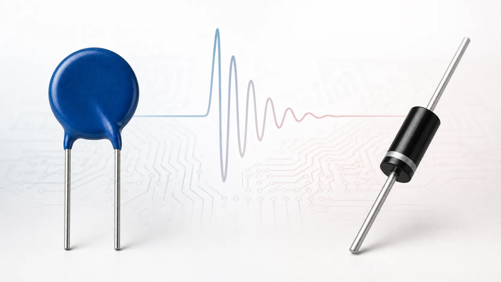
A metal-oxide varistor (MOV) and a transient-voltage-suppression (TVS) diode can both limit short overvoltage events, but they do not behave identically. An MOV is a bidirectional, voltage-dependent ceramic resistor. A TVS diode is a semiconductor avalanche device available in unidirectional and bidirectional versions.
Short answer: MOVs are widely used where broad voltage coverage and higher surge-energy handling are important, especially on power inputs. TVS diodes are often preferred when the protected circuit needs a more tightly controlled clamping characteristic and fast semiconductor response. The correct choice depends on the waveform, source impedance, operating voltage and failure consequences—not the component name alone.
How an MOV Works
An MOV normally presents high resistance. When the voltage rises into its nonlinear conduction region, current increases rapidly and the device limits the voltage across the protected line. The response is inherently bidirectional, so a standard MOV does not have positive and negative terminals.
MOVs are available as through-hole discs, molded surface-mount devices and multilayer varistors (MLVs). Their ratings vary from board-level electrostatic-discharge protection to much higher-energy power-line applications. See What Is a Varistor? for the basic operating regions and voltage terms.
How a TVS Diode Works
A TVS diode operates in avalanche breakdown. Below its standoff voltage, current is low. When a transient drives the device above breakdown, it conducts strongly and diverts current away from the load. A unidirectional TVS is normally used on direct-current (DC) rails; a bidirectional TVS can protect alternating or bipolar signals when its ratings and capacitance are suitable.
The words “fast” or “low clamp” are not enough to select a TVS. Its working standoff voltage, breakdown range, clamping voltage, pulse-power waveform, junction capacitance, leakage and package must match the real circuit.
MOV vs TVS Diode at a Glance
| Comparison | MOV | TVS diode |
|---|---|---|
| Technology | Nonlinear metal-oxide ceramic | Semiconductor avalanche junction |
| Polarity | Inherently bidirectional | Unidirectional or bidirectional |
| Common circuit position | Power input, mains, local board protection | DC rails, semiconductor nodes, interfaces |
| Clamping characteristic | Voltage rises with surge current; wide product range | Often tighter at a defined current, but still current dependent |
| Energy capability | Can be high in larger disc or molded products | Depends on package and specified pulse-power waveform |
| Capacitance | Varies widely; standard MLVs may be significant | Ranges from ultra-low-capacitance arrays to high-power devices |
| Aging | Repeated or excessive stress can shift leakage and varistor voltage | Normally stable below rating; excessive pulses can cause junction failure |
| Failure concern | Leakage increase, thermal runaway, short or open circuit | Short or open circuit after overstress, depending on device and fault |
1. Operating Voltage Comes First
For an MOV, the maximum continuous alternating-current (AC) or DC voltage must exceed the highest normal operating condition with suitable margin. The nominal varistor voltage is not the normal operating voltage.
For a TVS diode, the working standoff voltage must remain above the highest normal rail or signal voltage, including tolerance and charging conditions. Breakdown and clamping voltages occur above that level. Selecting either technology too close to the normal voltage increases leakage and unwanted conduction.
2. Compare Clamping at the Real Pulse Current
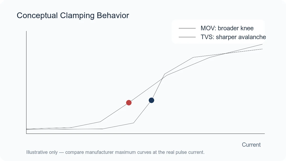
Clamping voltage is meaningful only with a stated current and waveform. An MOV value measured at 1 A cannot be compared directly with a TVS value specified at tens of amperes. The protected circuit must survive the worst-case residual voltage at the current that will actually flow after source impedance and upstream protection are considered.
MOV voltage rises as surge current rises. TVS diodes also have dynamic resistance, so their clamping voltage is not a fixed ceiling. Compare complete voltage-current curves and tolerance limits rather than one headline number.
3. Pulse Waveform and Energy Class
Peak current and pulse power are tied to waveforms. MOV datasheets often use an 8/20 μs current waveform for peak surge current and may use longer waveforms for energy. TVS data commonly uses 10/1000 μs or another specified pulse shape. A 600 W TVS rating under one waveform is not equivalent to 600 W under every transient.
A large disc MOV may absorb substantially more energy than a small semiconductor package, while a high-power TVS may outperform a small chip varistor in another circuit. Convert the actual transient into current, voltage, duration and repetition before comparing ratings.
4. Capacitance and Signal Integrity
On high-speed communication lines, capacitance can dominate the decision. Standard MOVs and MLVs may load the line, although low-capacitance MLV series exist. TVS arrays are available with very low capacitance for fast interfaces, but high-power TVS diodes can also have substantial capacitance.
Review capacitance at the stated frequency and bias. Validate insertion loss, eye diagram or interface margin when the protection component sits directly on a high-speed path.
5. Leakage, Aging and Repetitive Stress
MOV leakage rises with voltage and temperature and may increase after repeated high stress. Sustained abnormal overvoltage can cause heating and thermal runaway. Power-line designs often coordinate the MOV with a fuse, thermal disconnect or thermally protected MOV solution.
A TVS diode does not have the same grain-boundary aging mechanism, but it can still fail after excessive pulse energy, repetitive heating or sustained current. Use derating and repetitive-pulse information rather than assuming unlimited pulse life.
When an MOV Is Usually the Better Starting Point
- AC mains or high-voltage power input with a defined surge requirement
- High surge current or energy relative to available board space and cost
- Bidirectional protection without polarity concerns
- Applications where a broad range of disc, molded or multilayer options is useful
When a TVS Diode Is Usually the Better Starting Point
- Low-voltage DC rail feeding sensitive semiconductors
- Interface protection requiring low capacitance
- Applications where a tighter avalanche characteristic is required
- Pulse conditions that match an available TVS package and power rating
When to Use Both
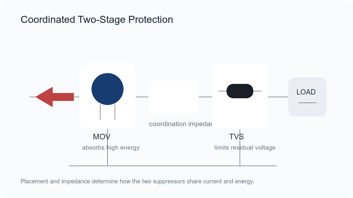
A coordinated two-stage network can use an MOV near the energy entry point and a TVS diode closer to the sensitive load. The MOV handles a large share of the incoming energy, while the TVS limits the downstream residual voltage. A series impedance, trace inductance, resistor, choke or other coordination element may be needed so the two devices share stress predictably.
Do not simply place two suppressors in parallel and assume they divide current evenly. Their tolerances and voltage-current curves determine which device conducts first and how much energy each absorbs.
Practical Selection Checklist
- Define the highest normal AC or DC voltage.
- Identify the transient standard, waveform, source impedance and pulse count.
- Calculate or measure the expected protection current.
- Set the maximum residual voltage the load can tolerate.
- Compare worst-case clamping curves at that current.
- Check energy, pulse power, capacitance, leakage and temperature derating.
- Review failure mode and fuse or thermal coordination.
- Validate the complete printed circuit board in the required test.
Frequently Asked Questions
Is a TVS diode always faster than an MOV?
Intrinsic response can be very fast for both. In a real circuit, placement, loop inductance and source impedance often dominate the first voltage overshoot. Compare system-level performance rather than a response-time claim alone.
Can a TVS diode replace a mains MOV?
Only if a specific TVS device is rated for the operating voltage, surge current, energy, safety and failure requirements. Many common TVS diodes are intended for lower-voltage DC circuits and are not direct mains-MOV replacements.
Can an MOV replace an ESD TVS array?
Sometimes a low-capacitance MLV is suitable, but not automatically. Check capacitance, clamping at the relevant ESD current, package routing and interface signal integrity.
Conclusion
MOV and TVS diode technologies overlap, but their strongest use cases differ. Select by normal voltage, transient waveform, clamping at real current, energy, capacitance, leakage, endurance and failure coordination. Where one device cannot meet both high-energy and low-residual-voltage requirements, a properly coordinated two-stage network may provide the better solution.












