

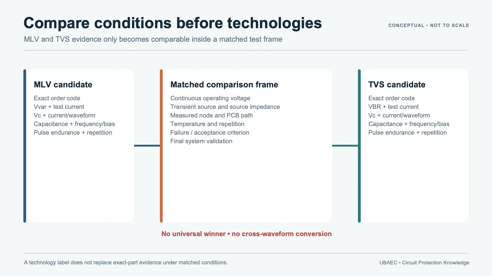
An MLV and a TVS diode can protect the same circuit location, but they are not the same device. A multilayer varistor (MLV) is a nonlinear ceramic component with internal electrodes. A TVS diode is a semiconductor avalanche device. Either technology may be the better candidate in a particular design, yet neither is the universal winner.
The useful question is not “Which technology is better?” It is “Which exact part produces an acceptable result under this rail voltage, transient waveform, source impedance, signal bandwidth, temperature, layout and lifetime requirement?”
If the product names themselves are unclear, begin with the MLV terminology and product-boundary guide.
MLV and TVS Diode: The Core Difference
| Comparison area | MLV | TVS diode | What must be verified |
|---|---|---|---|
| Technology | Voltage-dependent ceramic varistor structure | Semiconductor avalanche junction | Exact construction and manufacturer series |
| Polarity/configuration | Normally bidirectional in its basic two-terminal form | Available in unidirectional and bidirectional configurations | Line polarity, reverse behavior and circuit topology |
| Voltage fields | Commonly VDC/VAC, varistor voltage and clamping voltage | Commonly working standoff, breakdown and clamping voltage | Definitions, test current, tolerance and temperature |
| Capacitance | Strongly family-, size- and construction-dependent | Strongly die-, package- and topology-dependent | Maximum value, frequency, bias and signal-integrity evidence |
| Pulse capability | Specified by exact current, waveform, energy and repetition conditions | Specified by exact peak-power/current, waveform and pulse-duration conditions | Matched waveform, source impedance, duty and failure criteria |
| Integration | Discrete, multi-element, array and filtering structures exist | Discrete and multi-line/steering-array structures exist | Pinout, per-line/package ratings and current path |
This table describes comparison categories, not guaranteed advantages. An exact low-capacitance MLV may load a line less than one TVS candidate and more than another. The same limitation applies to clamp voltage, leakage, package size, energy and lifetime statements.
Translate the Datasheet Fields Before Comparing Values
Similar-looking voltage numbers often represent different measurement points. Record each field separately:
- Continuous operating limit: MLV datasheets may use maximum direct-current voltage (VDC) or alternating-current voltage (VAC); TVS datasheets commonly use working standoff voltage. Confirm whether the rail, tolerance and abnormal operating states remain below the applicable limit.
- Reference or breakdown point: an MLV varistor voltage is measured at a stated current such as V1mA or V0.1mA. A TVS breakdown voltage also has a specified test current and tolerance. Neither value is automatically the normal rail or the final clamp level.
- Clamping voltage: retain the injected current and waveform. A surge Vc value and a dynamic ESD clamp waveform are different measurements, even when both use the word “clamp”.
- Pulse rating: keep current, pulse shape, duration, source impedance, repetition count, interval and temperature with the value. Peak power, peak current and energy are not interchangeable labels.
The MLV datasheet parameter guide owns the detailed definitions and matched-condition rules.
Do Not Select by “Response Time” Alone
Manufacturer comparison papers may describe selected MLVs as faster, smaller or more durable than selected TVS diodes. For example, a Bourns MLV-versus-TVS comparison evaluates selected devices and test conditions. Such results belong to the named parts, package, fixture, waveform and operating range; they cannot be converted into a general technology law.
On a real printed circuit board (PCB), lead and trace inductance, connector geometry, return path, probe method and the location of the protection device can influence the observed overshoot. A nominal response-time statement therefore does not replace a dynamic voltage/current measurement on the final layout. Review the MLV PCB layout guide before interpreting a clamp waveform.
Capacitance and Signal Integrity
Capacitance can be a primary constraint on data, radio-frequency (RF) and sensor lines. Use a maximum—not only a typical—value at a disclosed frequency and bias. Then confirm whether the supplier provides insertion loss, scattering parameters (S-parameters) or other relevant high-frequency data for the exact device and package.
A “low-capacitance” label does not establish suitability for Universal Serial Bus (USB) 3.x, High-Definition Multimedia Interface (HDMI), DisplayPort or another high-speed interface. The interface, differential impedance, layout and complete channel need validation with the exact protection device installed.
Leakage, Temperature and Continuous Operation
Compare leakage at the actual operating voltage and temperature, not at unrelated test points. Include rail tolerance, bias polarity, standby-current limits and any derating required by the datasheet. A part that looks acceptable at room temperature may not meet leakage or clamp objectives across the full mission profile.
For both technologies, package thermal path and pulse spacing matter. Do not infer repetitive capability from a single-pulse rating, and do not infer long-pulse or load-dump performance from a short surge test.
Ageing, Failure Behavior and Protection Coordination
MLVs and TVS diodes have different material systems and degradation mechanisms, but neither should be described as universally maintenance-free or failsafe. Repetitive electrical stress, excessive energy, temperature, board damage, contamination and assembly defects can change the protection result.
Define what happens if the device becomes leaky, short, open or otherwise degraded. Coordinate fusing, current limiting, series impedance, upstream protection and fault monitoring where the hazard requires it. Component qualification or a supplier application claim does not guarantee equipment compliance; see MLV reliability, standards and failure modes.
A Matched-Condition Comparison Checklist
- Record the exact manufacturer, series, order code, package and lifecycle state.
- Confirm MLV construction or TVS-diode topology and polarity.
- Match normal rail, tolerance, abnormal voltage and continuous rating.
- Keep varistor/breakdown voltage definitions and test currents separate.
- Compare clamp behavior at the same injected current, waveform, fixture and temperature.
- Match pulse duration, source impedance, repetition, interval and acceptance criteria.
- Compare maximum capacitance, test frequency, bias, leakage and signal-integrity data.
- Check package, placement, return path, creepage/clearance and assembly constraints.
- Review temperature, ageing, failure state, qualification and protection coordination.
- Test both candidates on the final PCB and document the decision.
The MLV selection workflow turns these checks into a broader engineering process.
Two Typical Decision Paths
High-speed or low-current signal line
Start with maximum capacitance, leakage, bandwidth evidence and the permitted dynamic clamp at the protected IC. Compare an exact low-capacitance MLV with exact TVS/ESD-diode candidates, then measure insertion loss or eye performance and system ESD behavior on the final layout.
DC power or control line
Start with continuous voltage, abnormal rail behavior, transient source, pulse duration, energy/current demand and fault consequence. Compare clamp voltage and thermal behavior under the real source impedance. Add coordinated protection when neither single component safely covers every event.
Summary
MLV versus TVS is not a one-column comparison. Translate the voltage fields, match the waveform and current, retain capacitance and leakage conditions, include package and temperature, and test the final current path. The correct outcome may be an MLV, a TVS diode, another protection technology or a coordinated combination.
Continue Reading
- MLV Datasheet Parameters and Test Conditions
- How to Select an MLV
- MLV vs SMD MOV and Disc MOV
- Ask UBAEC
Official Technical References
The following first-party, standards-organization or publisher records support the technical boundaries used in this article. Always verify the current revision and the exact product scope before design release.
- Multilayer Varistors technology and product overview
- Comparing MLV vs. TVS Diode Circuit Protection Characteristics
- Advantages of Varistors and Their Applications in the Automotive Field
- Chip Varistor product lineup
- MLVC high energy multilayer varistor datasheet
- NV73DL Multilayer Type Metal Oxide Varistors for Automotive











