

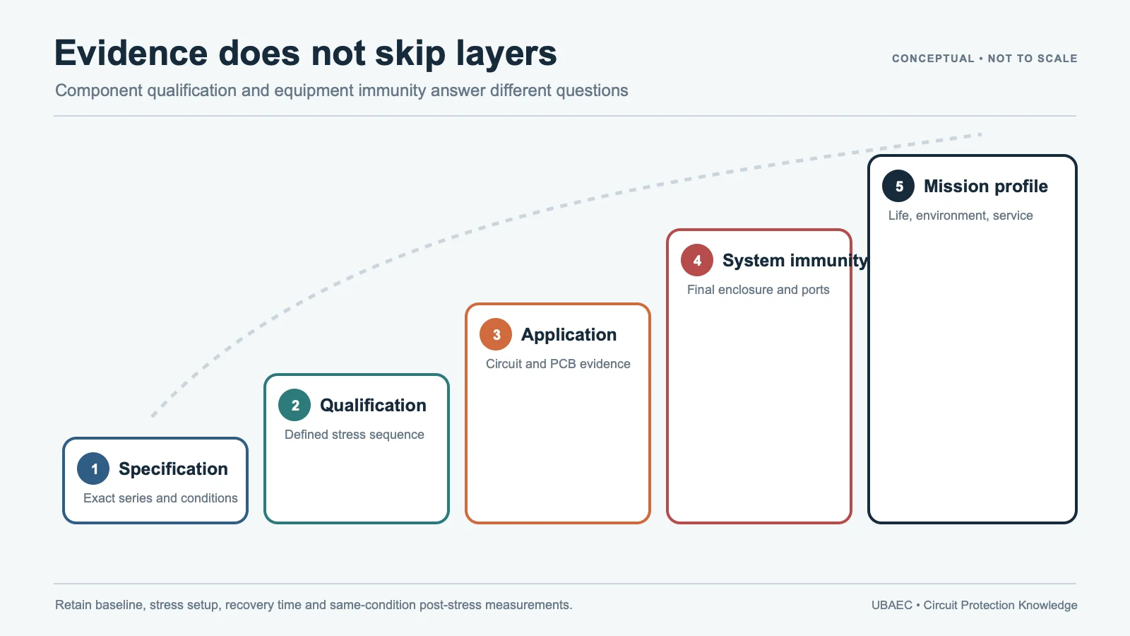
A multilayer varistor (MLV) can be within its datasheet limits and still fail in an unsuitable circuit, assembly or mission profile. Reliability therefore depends on four connected questions: what was tested, what the test object was, which conditions and acceptance criteria applied, and whether the final system was validated.
Five Evidence Layers That Must Stay Separate
- Component specification: definitions, ratings and tests for the component class or exact part.
- Passive-component qualification: stress-test evidence such as the Automotive Electronics Council’s AEC-Q200 document, tied to a declared family/order code and revision.
- Equipment/module immunity: International Electrotechnical Commission (IEC) 61000-4-x or automotive tests on a printed circuit board (PCB), module, equipment or vehicle configuration.
- Application evidence: measured waveform, layout, coordination and operating environment for the design.
- Mission-profile validation: final electrical, environmental, mechanical and safety evidence over the required life/profile.
No layer substitutes for another. A component’s rating or qualification does not by itself prove equipment, module or vehicle compliance.
How to Read Common Standards References
| Reference | Primary test object/scope | Boundary |
|---|---|---|
| IEC 61051-1 / -2 | Varistor component specification framework | Not a named product pass or equipment-immunity result |
| AEC-Q200 | Passive-component qualification under declared scope | Not EMC immunity, life guarantee or universal automotive suitability |
| IEC 61000-4-2 | Equipment electrostatic discharge (ESD) immunity | Not package-handling sensitivity or an independent MLV kilovolt rating |
| IEC 61000-4-4 / -4-5 | Equipment electrical fast transient (EFT)/burst and surge immunity | Generator, coupling, source impedance, repetition and criteria remain required |
| International Organization for Standardization (ISO) 10605 | Automotive module/vehicle ESD | Not AEC-Q200 qualification |
| ISO 7637-2 / -3 | Automotive supply-line and coupled non-supply-line transients | Exact pulse and test topology must remain separate |
Always state edition/revision, test object, severity, waveform/network, mounting, repetition and acceptance criteria. Legacy supplier wording stays tied to the legacy document; it cannot be silently upgraded to a newer standard edition. Likewise, an AEC-Q200 Rev D claim remains Rev D until current part-specific Rev E evidence exists.
Electrical and Thermal Failure Paths
Continuous overvoltage can increase leakage and self-heating. If the circuit supplies enough sustained current, temperature and leakage may reinforce each other and progress toward thermal damage. Use exact model voltage/temperature limits and coordinate current limiting, fusing or upstream protection where a fault can continue.
One-shot survivability is not repetitive life. Pulse waveform, peak, duration, source impedance, count, interval, bias and ambient temperature influence cumulative stress. Monitor Vvar, leakage, capacitance, appearance and function before and after representative endurance tests.
ESD and Grain-Boundary Degradation
Academic studies on zinc-oxide (ZnO) chip-varistor specimens link severe ESD exposure to grain-boundary barrier changes and shifts in leakage, capacitance or nonlinear behavior. One peer-reviewed study of ESD-stressed ZnO chip varistors provides mechanism evidence for its tested specimens and conditions; it does not establish a commercial product’s IEC 61000-4-2 rating, life or universal material superiority.
Mechanical and Assembly Failure
Ceramic bodies can crack under PCB bending, depanelization, connector/screw forces, shock, CTE mismatch or unsuitable pad/solder geometry. Reflow or flow-solder conditions can also damage terminations, solder joints or the ceramic body. No universal safe bend value, pad dimension or solder profile applies to every part.
Use the exact series guidance and the MLV layout, mounting and soldering guide.
Humidity, Contamination and Surface Effects
Humidity, condensation, ionic contamination, cleaning residue and damaged surface protection can increase leakage or corrosion risk. Steady damp heat and cyclic-condensing tests are different methods. Record temperature, relative humidity (RH) or cycle, bias, duration, recovery and acceptance criteria.
Failure State Is Not Universal
Depending on stress, construction, mounting and available current, an MLV may become shorted, resistive/leaky, intermittent or open. Some named products use open-mode or failsafe architectures, but those claims apply only to exact constructions and do not replace system protection or hazard analysis.
Reliability Review Checklist
- exact order code, datasheet revision and lifecycle;
- standard edition and test object;
- severity, waveform/network, repetition, bias and temperature;
- pre/post drift limits and functional acceptance;
- mounted-board mechanical and solder process;
- expected short/open/leaky failure consequences;
- fuse/current-limit/upstream protection coordination;
- final module/equipment test and retained evidence.
Use MLV datasheet parameters and test conditions for field definitions and How to Select an MLV for the engineering workflow.
Summary
Reliable MLV use requires matched component evidence, controlled assembly, measured application stress and final-system validation. A standard name is not a pass result, qualification is not system compliance, and one pulse rating is not a lifetime claim.
Continue Reading
- MLV Datasheet Parameters and Test Conditions
- How to Select an MLV
- MLV PCB Layout, Mounting and Soldering
- MLV Knowledge Map
Official Technical References
The following first-party, standards-organization or publisher records support the technical boundaries used in this article. Always verify the current revision and the exact product scope before design release.
- Safety precautions for chip-type multilayer varistors
- Degradation of potential barriers in ZnO-based chip varistors due to electrostatic discharge
- AEC-Q200 Rev E – Stress Test Qualification for Passive Components
- IEC 61051-1:2018 – Varistors for use in electronic equipment – Part 1: Generic specification
- ISO 10605:2023 – Road vehicles – Test methods for electrical disturbances from electrostatic discharge
- IEC 61051-2:2021 – Varistors for use in electronic equipment – Part 2: Sectional specification for surge suppression varistors












