

Multilayer varistor (MLV), surface-mount device metal-oxide varistor (SMD MOV) and disc MOV are not interchangeable labels. MOV describes a broad metal-oxide-varistor technology family. SMD describes surface mounting. Disc describes a physical construction. MLV identifies a multilayer ceramic construction.
The same words may appear in distributor filters or manufacturer portfolios, but a shared MOV or SMD label does not make the parts electrically equivalent. Confirm the construction and exact series before comparing voltage, current, energy, safety or application role.
For the full naming system, see MLV terminology and product boundaries.
Three Construction Classes
| Class | General construction | Common package/form | Primary comparison rule |
|---|---|---|---|
| Ceramic MLV | Nonlinear ceramic layers with embedded internal electrodes and external terminations | Leadless chip; discrete, multi-element or filter topology | Use the exact MLV series/order-code data and its stated test conditions |
| Molded or plastic-encapsulated SMD MOV | Varistor element inside a molded or plastic surface-mount body | Manufacturer-specific SMD outline, often visually larger than small chips | Keep outside the ceramic-MLV matrix unless multilayer construction is separately confirmed |
| Disc/radial MOV | Sintered varistor disc with leads and coating or encapsulation | Radial through-hole device | Do not transfer its surge, energy, mains or safety ratings to a chip MLV |
This classification is about construction, not a guaranteed performance order. Large and small products exist, and manufacturers also offer special high-voltage or higher-energy MLV families. Every capability remains exact-model specific.
Why “SMD Varistor” Is an Umbrella Term
A surface-mount varistor may be a bare ceramic MLV, a molded MOV, a monolithic/disk-like element adapted for reflow or another structure. Package appearance cannot resolve the difference. Use the official construction description, cross-section, material statement or family datasheet.
KEMET’s VP documentation, for example, describes a plastic-encapsulated surface-mount varistor positioned as an alternative to selected leaded disc sizes. That is evidence for the VP family, not a definition of every SMD MOV. Eaton’s surface-mount MOV portfolio likewise illustrates why the package category must not be treated as an MLV synonym.
Why MOV Ratings Cannot Move Across Constructions
Construction changes active material volume, electrode geometry, current distribution, thermal path, termination, mechanical behavior and installation context. Those differences affect how a manufacturer defines and validates the part.
Before comparing values, keep these fields attached:
- maximum continuous direct-current voltage (VDC) and alternating-current voltage (VAC), including temperature derating;
- varistor voltage and its test current;
- clamping voltage, injected current and waveform;
- maximum peak current, pulse shape, repetition and interval;
- energy with waveform or pulse duration;
- capacitance with frequency, bias and maximum/typical status;
- leakage, temperature range, qualification, safety and lifecycle scope.
An 8/20 µs peak-current value is not a 10/1000 µs energy value. Neither automatically proves automotive load dump, International Electrotechnical Commission (IEC) installation surge or repetitive lifetime. The MLV parameter and test-condition guide explains these fields in detail.
Typical Roles Without Turning Them Into Rules
Ceramic MLV
MLVs are widely used for board-level ESD and low-to-moderate transient protection, with compact chip, array and filtering options. Capacitance and pulse capability vary substantially by family. A small ESD-oriented MLV and a large high-energy MLV should not be summarized by one range.
Molded SMD MOV
A molded surface-mount MOV may serve a higher-energy or power-oriented SMD role while avoiding radial leads. This is a product-family tendency, not a transferable rating. Confirm reflow profile, package thermal behavior, fault response and exact pulse data.
Disc MOV
Disc MOVs are commonly associated with power, mains and higher-energy surge duties. That context brings installation category, prospective current, safety approvals, enclosure, fusing or thermal protection and failure behavior into the design. A disc MOV’s size or joule value does not create a safe equivalent MLV.
The AC-Mains and High-Energy Boundary
A generic small MLV should not be presented as a replacement for a disc MOV or surge protective device on an AC input. Some manufacturers publish named high-voltage or higher-energy MLV series, but those are model-specific exceptions. Use requires exact VAC/VDC ratings, surge duration and source impedance, thermal/failure testing, safety evidence, fault-current coordination and final installation validation.
What to Do With Ambiguous Product Names
If a source says “SMD varistor,” “chip MOV” or “MLV process” without a clear construction statement, record the product as unresolved. Do not infer the internal structure from appearance, package size, distributor category or a translated title.
If first-party documents use conflicting terms or do not disclose enough construction information, keep the product outside a ceramic-MLV comparison until the manufacturer supplies adequate evidence. An unresolved classification is safer than moving voltage, current or energy data into the wrong product matrix.
Construction-First Selection Workflow
- Record manufacturer, exact series, order code, revision and lifecycle state.
- Verify ceramic multilayer, molded/plastic SMD, disc/radial or unresolved construction.
- Define the circuit rail, abnormal voltage and transient source.
- Match voltage definitions, test current, waveform, source impedance and repetition.
- Compare thermal path, package, mounting, land pattern, clearance and assembly limits.
- Check safety, qualification and failure-state evidence for the exact use.
- Plan fusing, thermal protection, current limiting or coordinated stages where required.
- Validate the exact component and PCB under electrical, thermal and fault conditions.
Use the MLV selection workflow for the complete decision sequence and MLV reliability, standards and failure modes for evidence-layer and fault controls.
Summary
MLV is a multilayer ceramic construction. Molded SMD MOV is a separate surface-mount construction. Disc MOV is a leaded single-body construction. MOV and SMD labels alone do not authorize rating transfer. Compare only exact parts with their voltage definitions, waveform, current, energy, temperature, package, safety and installation conditions intact.
Continue Reading
- MLV Terminology and Product Boundaries
- MLV Datasheet Parameters and Test Conditions
- How to Select an MLV
- MLV Reliability, Standards and Failure Modes
Official Technical References
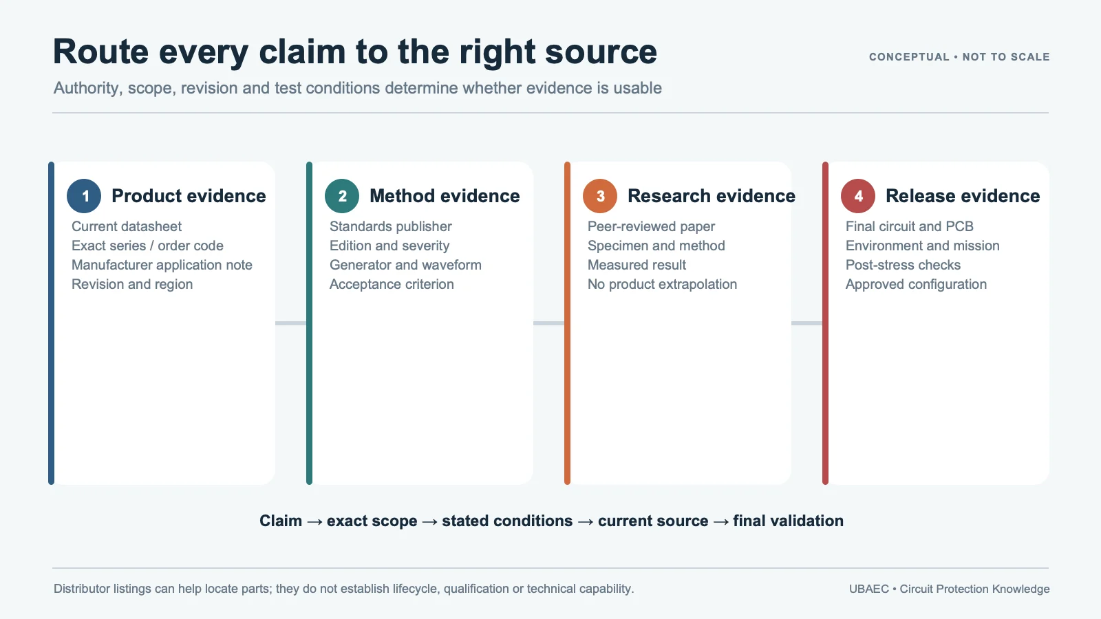
The following first-party, standards-organization or publisher records support the technical boundaries used in this article. Always verify the current revision and the exact product scope before design release.












