

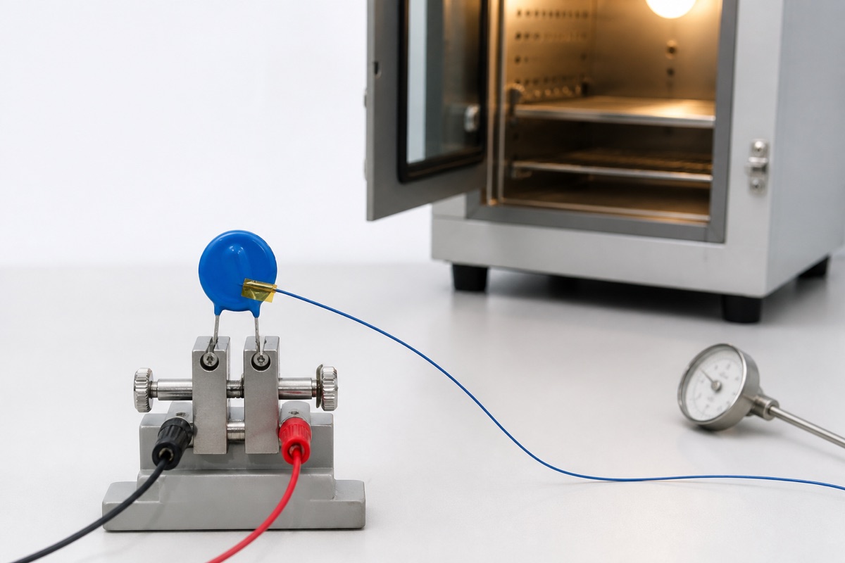
An MOV datasheet may list an operating-temperature range extending to 125°C. That does not automatically mean every voltage, surge-current, energy, and power rating remains at 100% up to 125°C. The operating range defines an environmental boundary; the derating curves define what the device may do inside that boundary.
Two mistakes are common. One is using the room-temperature or 85°C table maximum at a hotter location without correction. The other is multiplying every datasheet value by one percentage taken from a curve that applies only to current, energy, and power. Temperature derating has to be applied parameter by parameter.
Four temperature statements that are not interchangeable
Operating-temperature range
This range states where the component may operate, subject to all other ratings and derating rules. Its upper endpoint is not necessarily the highest temperature for full-rated operation.
Rating reference temperature
Maximum continuous voltage, peak surge current, energy, and average power may be tabulated at 85°C, 105°C, 125°C, or another stated condition. The column heading and footnotes are part of the rating. Copying the number without its temperature removes essential design information.
Derating start temperature
This is where a specified rating begins to fall below 100%. It is series-dependent. TDK’s SIOV general information assigns different product families to different temperature curves and identifies operating voltage, surge current, energy absorption, and average power as quantities that may require derating. A Littelfuse TMOV datasheet, by contrast, shows current, energy, and power beginning to fall above approximately 85°C. Neither curve is a universal MOV rule.
Storage-temperature range
Storage limits apply to an unpowered component under the stated conditions. They do not prove that MCOV, leakage, or surge ratings are available at the storage-temperature endpoint.
Which ratings may change at high temperature?
Peak surge current
A hotter MOV starts with less thermal headroom. Where the datasheet requires current derating, apply the curve to the rating for the relevant waveform and pulse count. Do not apply it only to the largest one-pulse number while ignoring repetitive-pulse curves.
Energy absorption
Energy ratings are tied to waveform or duration as well as temperature. A calculated joule value below the room-temperature maximum may still exceed the high-temperature permissible value. The temperature curve and the pulse-duration or repetition limit both have to pass.
Average power
Periodic surges create average dissipation, and leakage at the continuous applied voltage adds self-heating. TDK’s selection procedure evaluates periodic energy divided by pulse interval as average power. In a hot enclosure, this limit can become controlling before the one-pulse maximum is reached.
Maximum continuous operating voltage
Whether AC or DC MCOV must be reduced depends on the exact series. TDK documents families where operating voltage is included in temperature derating, while other high-temperature products retain full voltage rating to a stated threshold. If a curve is titled only for current, energy, and power, do not silently extend it to voltage—and do not assume voltage is unaffected without checking the product table.
Use the temperature at the MOV, not the room temperature
The relevant ambient is the local environment around the component. Rectifiers, power resistors, magnetics, heat sinks, closed enclosures, and restricted airflow can make it much hotter than the room. A second pulse may also arrive before the MOV has returned to its initial thermal state.
Use measurements from the worst credible mounting location or a validated thermal model. Keep local air temperature, case-surface temperature, and the datasheet’s defined ambient condition distinct; they are related but not automatically identical.
A practical temperature-derating workflow
- Identify the exact device. Record manufacturer, family, and full ordering code; do not select a curve from a generic marking such as 471K.
- Define the hot location. Include maximum load, high line, enclosure, airflow, and neighboring heat sources.
- Read the reference conditions. Note the temperature attached to each table maximum and the stated operating range.
- Select the correct family curve. Mark exactly which quantities—voltage, current, energy, or power—the curve covers.
- Combine independent derating rules. Apply temperature limits together with waveform, pulse count, pulse interval, and repetitive-duty curves.
- Recheck the protection window. Verify MCOV margin, clamping voltage, leakage, fuse behavior, and thermal-disconnect coordination.
- Validate the assembly. Measure local temperature and perform representative surge and abnormal-overvoltage tests in the intended enclosure.
Series differences matter
High-temperature MOV families can have very different thresholds. Littelfuse’s Xtreme-series material shows peak-current and energy derating beginning at a higher temperature than the TMOV curve. TDK also offers compact families with no derating to 105°C and specialized products with still different limits. These examples demonstrate that the threshold belongs to the family; they do not authorize the same threshold for a conventional MOV.
Automotive MLVs, thermally protected MOVs, molded SMD MOVs, and ordinary radial discs also have different construction and heat paths. Use the documentation for the actual product type.
FAQ
If the operating limit is 125°C, can the full surge rating be used at 120°C?
Not from that statement alone. Check the current and energy derating start temperature; many devices begin derating before the maximum operating-temperature endpoint.
If the curve shows 50%, should every rating be multiplied by 0.5?
No. Apply the percentage only to the quantities named by the curve or product note. Voltage, surge current, energy, and power may follow different rules.
Is a high-temperature steady-state test enough?
It checks part of the leakage, self-heating, and continuous-voltage risk. If the product must withstand surges while hot, pulse capability and the complete disconnect path also require validation at the relevant temperature.
Practical conclusion
MOV temperature derating is not simply a discount applied to peak current. Identify the exact family, reference temperature, and quantities covered by each curve, then check voltage, surge current, energy, average power, repetitive pulses, and thermal protection together. Maximum operating temperature is an environmental boundary, not a full-rating guarantee.
Continue with MOV Single-Pulse vs Repetitive Surge Ratings, MOV Key Parameters, MOV Failure Modes and Thermal Protection, and How to Select an MOV. For a part review, send the full ordering code, maximum local temperature, operating voltage, waveform, and pulse count through the UBAEC contact page.












