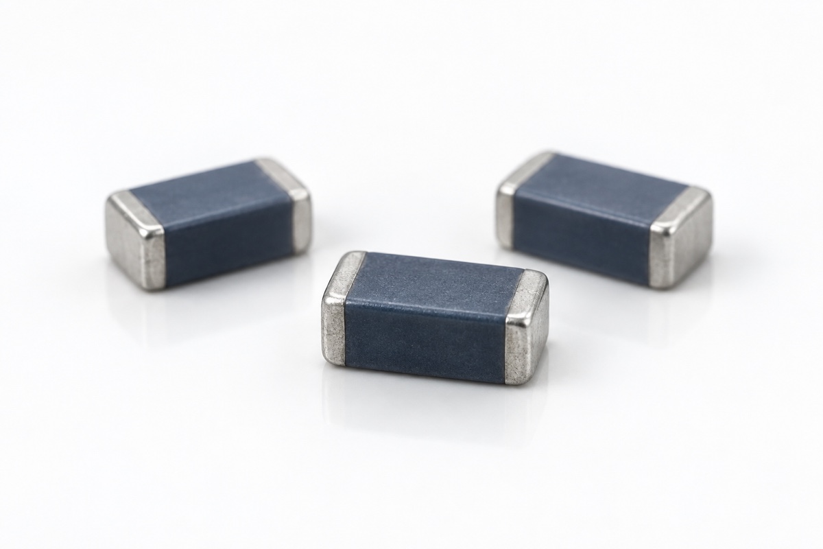
A multilayer varistor (MLV) datasheet lists 4.7 pF typical capacitance. Is 4.7 pF the number that should be placed in a high-speed channel model and treated as the finished design? No. A typical value is useful for a nominal model, but it is not automatically a production ceiling. Worst-case insertion loss, return loss, or eye-margin analysis needs a stated maximum, a tolerance-derived upper limit, or distribution evidence that can be reviewed. The measurement frequency, AC test level, temperature, and bias conditions must remain attached to the number.
Passing a calculation with maximum capacitance does not prove that the interface will pass. An MLV is not an ideal capacitor. Its package, pads, vias, branch geometry, return path, and nonlinear clamping behavior all participate in the assembled result. The practical method is to use datasheet fields to establish boundaries, then close the remaining uncertainty with a model appropriate to the channel bandwidth and measurements on representative hardware.
Typical, maximum, and tolerance limits answer different questions
A typical value normally describes representative production or a central observed level. Unless the manufacturer explicitly defines otherwise, it is not a per-device acceptance limit and does not establish that every shipped part will remain below it. A maximum value, or the upper end of a specified nominal tolerance, is more suitable for procurement and worst-case analysis. Even that limit applies only to the product scope and test conditions stated in the document.
TDK’s automotive MLV presentation provides a clear field-level example. For a 100BASE-T1 application it lists CT0402S20AHSG_P at 4.7 pF with 5.7 pF maximum in parentheses. For a 1000BASE-T1 application it lists AVRH10C101KT1R1NE8 at 1.1 pF with 1.4 pF maximum. Those figures illustrate the relationship between typical and maximum values for the named devices in that source. They are not generic MLV limits, and the measurement conditions still have to be taken from the applicable product documentation.
A capacitance number is incomplete without its test conditions
Consider TDK CT0805K20G_X1. Its version 1 datasheet dated 2026-02-19 specifies 300 pF typical at 1 kHz, 1 V, and 25 °C. That field is useful for understanding the order of magnitude of this exact part under the stated small-signal condition. It is neither a 300 pF guaranteed ceiling nor a complete impedance model at 100 MHz or 1 GHz. Two candidates both marked “5 pF” should not be ranked as equivalent if one was measured at 1 kHz and the other at 1 MHz.
A reviewable record should include test frequency, AC level, DC bias, temperature, fixture, de-embedding boundary, and whether the value is typical, nominal with tolerance, or maximum. When a document omits a condition, the missing information remains an engineering uncertainty. Ask the manufacturer for clarification or keep the candidate in a validation state; do not invent a limit from a typical value.
Use capacitance for a first-order loading check, not a final verdict
Below self-resonance, while a capacitive approximation remains reasonable, the magnitude of ideal capacitive reactance is |XC| = 1/(2πfC). At 100 MHz, 5 pF is about 318 Ω and 6 pF is about 265 Ω. The calculation shows that a 20% capacitance change alters the shunt load. It does not directly predict insertion loss because the answer also depends on the connection node, source and load impedances, differential or common-mode path, package parasitics, and branch geometry.
Data rate divided by two is not a universal frequency for checking a digital interface. Fast edges contain energy above that frequency, and the relevant bandwidth is set by the transmitter, receiver, channel, and interface specification. Use the frequency range and masks required by the target interface. If a manufacturer provides S-parameters, impedance curves, or a documented equivalent model, use them only within their stated scope rather than extending a low-frequency capacitance number into an all-frequency model.
Build nominal, upper-bound, and mismatch cases
| Case | Recommended input | Purpose | What it does not prove |
|---|---|---|---|
| Nominal | Typical capacitance and nominal layout parasitics | Compare directions and correlate during debug | Coverage of all production parts |
| Upper bound | Maximum or tolerance ceiling plus reasonable pad, via, and branch parasitics | Check worst-case loss, reflection, edge, and eye margin | Finished-board compliance |
| Mismatch | Defensible high and low values on the two lines plus asymmetric layout | Inspect skew and differential-to-common-mode conversion | Guaranteed balance when no matching limit exists |
If the datasheet supplies only a typical value, do not apply an arbitrary “safety multiplier.” Request a maximum, statistical distribution, lot data, or interface model from the supplier. Another defensible path is to measure an adequate sample under a controlled fixture and build an internal limit that includes measurement uncertainty and lot coverage. Such sample evidence belongs to the system designer; it must not be rewritten as a manufacturer guarantee.
Differential links add a symmetry problem
Placing the same MLV part number on both conductors does not guarantee a balanced link. Device spread, pad size, via count, distance to the reference plane, and branch length can be different. Those asymmetries can convert differential energy into common mode even when average capacitance looks acceptable. For an MLV array, also determine whether the datasheet capacitance is defined per line to a common terminal, between a stated pair of terminals, or for the complete package, and check whether channel matching is actually specified.
Differential validation may therefore include differential insertion loss, differential return loss, and the mode-conversion quantities required by the interface. Eye, jitter, or time-domain measurements depend on the relevant specification. Two similar LCR-meter readings by themselves do not prove that the populated high-frequency channel is symmetrical.
Signal-integrity approval does not close the protection review
Lower capacitance usually reduces shunt loading, but it is only one selection dimension. Maximum continuous operating voltage, varistor voltage and test current, clamping voltage and pulse condition, leakage, required electrostatic-discharge (ESD) or surge level, temperature range, and reliability qualification still have to pass. Similar package and capacitance values are not evidence that two protection devices are interchangeable.
Layout has two objectives as well. A short protection branch can reduce inductance in the discharge path, while its pads, vias, and reference-plane discontinuities still affect the data channel. If the MLV is moved, the pads are reduced, or the return path is changed to recover eye margin, repeat the target system-level ESD test. Component ratings and qualifications do not replace validation of the finished assembly.
A reviewable selection and validation workflow
- Lock the interface standard, data rate, transmitter edge behavior, channel impedance, and the required loss, reflection, mode-conversion, and eye limits.
- Lock the complete MLV ordering code and document revision. Record typical capacitance, maximum or tolerance, and every stated test condition; leave missing fields unresolved.
- Use a nominal case to understand direction. Add package, pad, via, and branch parasitics to the upper-bound case, and build a separate mismatch case for differential links.
- Simulate over the interface’s required frequency range. Do not present a model outside the manufacturer’s stated range as a guaranteed part characteristic.
- Measure the applicable frequency- or time-domain metrics on representative boards and record fixture, de-embedding boundary, bandwidth, and temperature.
- Run the required ESD or surge system test on the real protection path, checking protected-node stress, functional behavior, and post-test device condition.
Frequently asked questions
Can an MLV with typical-only capacitance still be evaluated?
Yes, but the typical value cannot be treated as a guaranteed ceiling. Obtain supplier limit or distribution evidence, or manage the uncertainty with representative sample measurements, measurement uncertainty, and system margin.
Is the lowest capacitance always the best choice?
It is often easier on a high-speed channel, but the part must also satisfy operating voltage, clamping, leakage, ESD or surge, temperature, and reliability requirements. Minimum pF is not a complete selection rule.
Can a 1 kHz capacitance value predict GHz insertion loss?
No. It is one small-signal, low-frequency data point. High-frequency behavior also depends on the package, layout, and frequency-dependent model. Use applicable S-parameters, impedance data, or board measurements.
Does using the same part number on both differential lines guarantee matching?
No. Same part number does not mean individually paired parts, and the two mounting structures may differ. Unless a matching limit is specified, include component spread and layout asymmetry in worst-case analysis and hardware measurements.
Practical conclusion
Typical MLV capacitance answers what a representative device may look like; maximum capacitance or an explicit tolerance ceiling is the stronger input for the worst case. Both values remain conditional on the test method. A high-speed design should combine the component limit with layout parasitics and differential mismatch, then verify the result through channel measurements and system-level ESD testing.
Continue with MLV Datasheet Parameters and Test Conditions, How Multilayer Varistors Work, MLV Layout and Mounting, and the MLV Selection Guide.