

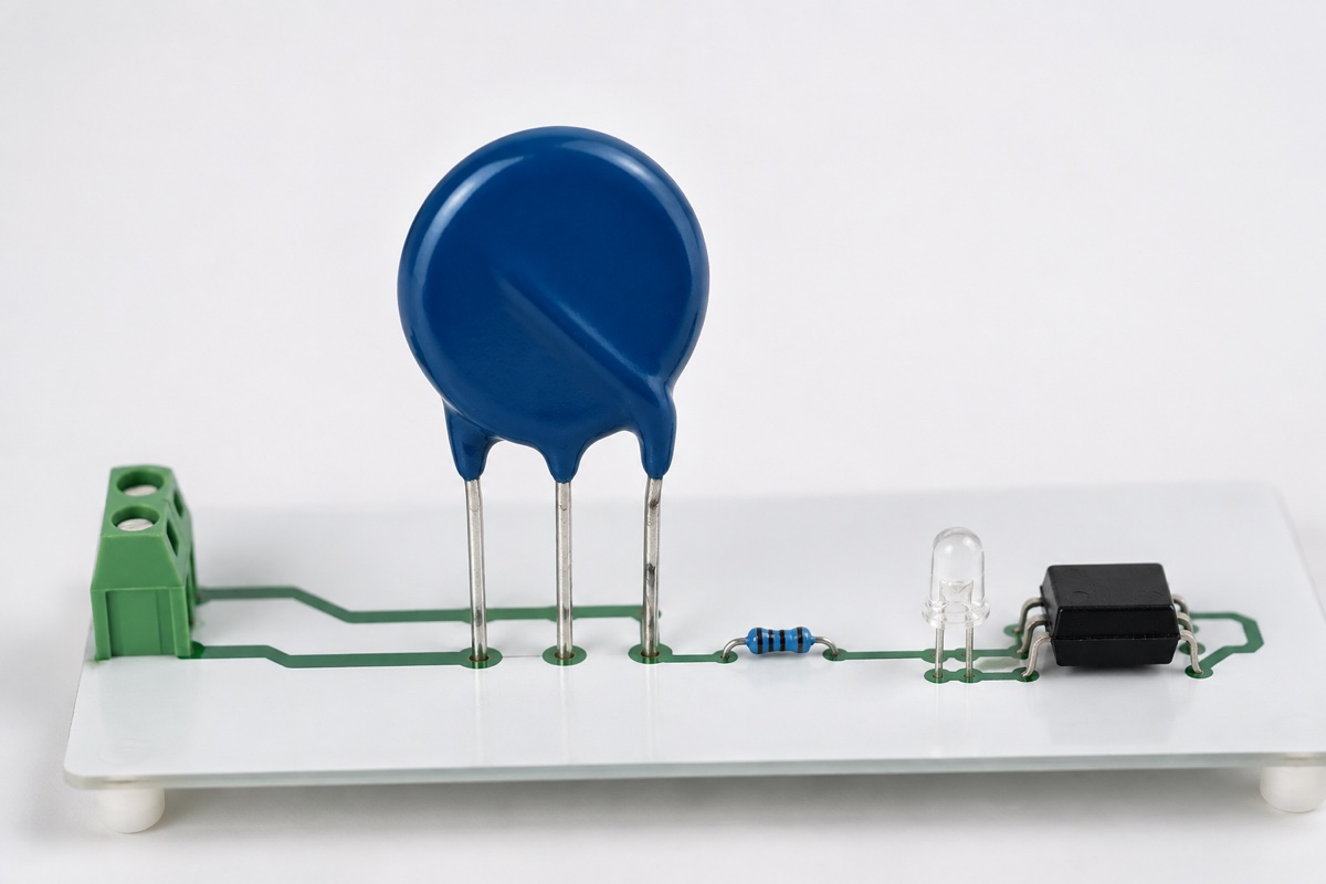
The third lead on a thermally protected metal oxide varistor (MOV) often invites the wrong first question. Designers ask whether it is normally open or normally closed before establishing what electrical node it belongs to. Although manufacturers may call it a monitor, indicator, or status lead, the name does not mean that it is an isolated relay contact or a logic-level output. In a mains application, connecting it directly to a microcontroller unit (MCU), programmable logic controller (PLC) input, or communications interface can bridge a hazardous-voltage circuit into the low-voltage control domain.
The device integrates a varistor and a thermally coupled disconnecting element. If abnormal overvoltage, degradation, or another electrical stress heats the MOV to the specified operating condition, the thermal element opens and removes the MOV from the line. A three-lead version exposes an additional node so the equipment can indicate whether the protection path remains intact. The correct wiring depends on the internal circuit and pin assignment for the complete ordering code, not simply on the presence of a third wire.
Identify the electrical node before choosing the alarm circuit
An isolated dry contact normally consists of a contact pair that changes state without carrying the monitored circuit’s potential into the receiving circuit. Most three-lead thermally protected MOV arrangements do not add a separate relay contact pair. The monitor lead is associated with the MOV and thermal-disconnect network, so it may remain a line-referenced node even though it carries only a small indication current. Every resistor, indicator, connector, and printed circuit board (PCB) trace connected to it must therefore be reviewed in the correct voltage domain.
The application diagrams in the Littelfuse iTMOV® datasheet illustrate this distinction. They show a local light-emitting diode (LED) indicator, an optocoupler with an alternating-current (AC) input that transfers the state across a galvanic-isolation barrier, and a relay circuit that removes power from the load after protection is lost. TDK likewise describes the third wire of its three-lead NT ThermoFuse™ varistors as a monitor output lead that can signal thermal-fuse activation to an LED. These examples establish a legitimate monitoring function, but they do not define the lead as a universal low-voltage output.
LED, optocoupler, and relay circuits serve different purposes
A local LED provides indication, not isolation
A high-voltage-side LED circuit can provide a simple visual indication of the thermal-disconnect state. In one manufacturer example, the LED is illuminated while the protection path is intact and turns off after the disconnect opens. That polarity and pin assignment cannot be assumed for every product. The current-limiting network must be calculated from the maximum continuous line voltage, not only the nominal supply, and its working voltage, power dissipation, tolerance, and temperature derating must all be checked.
An AC circuit also exposes an LED to reverse voltage unless the topology provides rectification or reverse protection. More importantly, the indicator remains part of the line-side circuit even if the LED itself operates at only a few volts. Its leads, solder joints, light pipe, enclosure opening, and service access must preserve the required creepage, clearance, and insulation. A low indication current does not make a mains-referenced node safe to touch.
An optocoupler transfers status across a defined boundary
When the status must reach a microcontroller, PLC, network interface, or another safety extra-low-voltage circuit, the line-side network can drive an appropriately rated optocoupler or isolated input. The review should cover the highest working voltage, input-current range, LED reverse stress, transient environment, insulation rating, and package creepage and clearance. On the receiving side, the logic must also distinguish thermal trip from loss of power and remain reliable as the optocoupler’s current transfer ratio changes with temperature and age.
Isolation is a property of the complete channel rather than a label supplied by one component. Copper spacing, PCB slots, connectors, pollution degree, overvoltage category, material group, and the required basic or reinforced insulation all contribute to the result. If a programming cable, shield connection, or shared ground reconnects the two domains elsewhere, placing an optocoupler next to the MOV does not make the finished design isolated.
A shutdown function needs a separate power-switching path
Opening the internal thermal element removes the MOV branch; it does not necessarily de-energize the product. Equipment can continue operating after its original surge-protection path has been lost. If the risk analysis requires an automatic shutdown, the monitor state must control a relay, contactor, or other switching device with suitable breaking capacity. Coil voltage and current, contact load, endurance, surge suppression, and the de-energized state must be evaluated independently. The monitor lead should not be expected to drive a coil unless the exact application documentation and ratings support that use.
Information needed before the schematic is released
| Question | Why it matters and what to verify |
|---|---|
| What is the complete part number? | A family may contain two- and three-lead versions, several lead forms, and different voltage classes. Review the ordering table, internal circuit, pin numbers, and mechanical drawing. |
| Which connections exist before and after a trip? | The answer determines the LED, optocoupler, or relay logic and its fail-safe state. Confirm it from the datasheet state diagram and a controlled check on the exact sample. |
| Which voltage domain contains the monitor node? | This determines whether a direct control connection is permitted and what insulation is required. Establish the maximum AC root-mean-square (RMS) or direct-current (DC) voltage relative to line, neutral, protective earth, and control ground. |
| Are all external parts adequately rated? | Low current does not guarantee acceptable working voltage, pulse withstand, or dissipation. Check resistor voltage and power ratings, indicator reverse stress, optocoupler input limits, and relay requirements. |
| What happens after protection is lost? | Local warning, latched service fault, remote reporting, and shutdown address different risks. Document the maintenance plan, start-up diagnostics, and defined safe state. |
This review must use the exact suffix shown on the bill of materials. Similar-looking parts can have different lead arrangements, monitor connections, and rating conditions. A continuity measurement on an unpowered sample may help confirm pin identity, but it cannot replace the datasheet or establish behavior at the thermal operating point. Such a measurement says nothing about line voltage, tolerance, temperature, insulation, or failure response.
What the third lead can report—and what it cannot
The monitor signal generally reports whether the thermal disconnect is intact or open. It does not measure remaining MOV life. Repetitive surges may shift varistor voltage or increase leakage before the temperature reaches the disconnect’s operating condition, so an “intact” indication does not prove that the MOV retains its original pulse capability. Maintenance intervals, surge-event records, leakage monitoring, or periodic electrical tests must be defined separately when the application requires them.
The indication channel also has failure modes of its own. An open LED, damaged limiting resistor, aged optocoupler, loose connector, failed relay, or defective controller input can create a false alarm or conceal a real loss of protection. If the alarm performs a safety-related function, inject representative open circuits, shorts, loss of power, and component drift during system validation. A monitor-circuit failure must not defeat the MOV’s thermal disconnect or introduce a hazardous voltage into the control side.
A healthy status indication does not demonstrate compliance of the complete surge protective device with UL 1449, IEC 61643, or an end-product standard. Component approvals, short-circuit current ratings, abnormal-overvoltage behavior, enclosure performance, and equipment-level coordination are separate evidence. The upstream fuse and the MOV’s internal thermal disconnect also address different fault mechanisms and time-current conditions; neither one can be omitted merely because the other is present.
Verification should cover more than one change of state
Begin by measuring the monitoring current, component dissipation, and temperature rise at nominal line voltage, the permitted maximum continuous voltage, and the expected ambient-temperature limits. Check for false indications during start-up, shutdown, brownouts, and normal line variation. Then use the manufacturer’s procedure, or an approved equivalent, to reproduce the thermal-disconnect state and confirm the indication, fault latching, remote message, and load response. Mains and thermal testing requires suitable equipment and qualified personnel; uncontrolled heating or ad hoc shorting is not a valid substitute.
Record two outcomes separately. The first is whether the protection branch exits safely, without sustained heating, arcing, or an unsafe leakage path after the MOV is disconnected. The second is whether the monitoring channel reliably reports the loss of protection under normal and single-fault conditions. Treating those as separate acceptance criteria prevents a working status lamp from being mistaken for proof that the whole protection design has passed.
Frequently asked questions
Can the third lead be connected directly to an LED?
Only when the exact manufacturer’s circuit permits it and the limiting network, reverse-voltage protection, power dissipation, maximum service voltage, and insulation distances are suitable. An AC-line indicator cannot be designed by choosing a resistor from the LED forward voltage alone. The complete branch remains a high-voltage circuit and needs verification at its worst-case operating conditions.
Can it connect directly to a microcontroller or PLC input?
Do not assume that it can. Establish the monitor lead’s potential relative to the power conductors, then use an optocoupler, relay, or isolated input that meets the working-voltage, transient, creepage, clearance, and failure requirements of the application. The logic should also avoid interpreting an unpowered monitor circuit as proof that protection is healthy.
Does thermal operation automatically switch off the equipment?
Usually not. The internal disconnect primarily removes the overheated MOV from its parallel protection branch. The load is de-energized only if the external design uses the monitor state to control the power path, or if another protective device opens. Whether continued operation is acceptable must come from the system risk analysis, with a clear maintenance response for equipment that remains energized.
Can a two-lead thermally protected MOV provide the same status?
A two-lead version has no dedicated monitor output, so a three-lead application circuit cannot simply be transferred to it. Choose a complete ordering code that explicitly provides monitoring, or develop a separate protection-state detection method and validate it as part of the equipment. Measuring continuity across the two power leads does not provide an equivalent independent status signal.
Bottom line: review the third lead as a line-side node first
The third lead of a thermally protected MOV can report operation of the internal thermal disconnect, but it is not inherently an isolated dry contact. Confirm the internal circuit and state logic for the complete part number before choosing a local LED, isolated optocoupler, or external shutdown relay. Until the datasheet establishes otherwise, treat the monitor connection as potentially line-referenced and apply the required component ratings, insulation distances, and fault-response design.
For the surrounding protection architecture, see MOV Fuses vs Thermal Disconnects, MOV Failure Modes and Thermal Protection, MOV Protection Circuit Basics, and MOV Standards and Approvals. Together, these pages cover the upstream fuse, the protected branch, common failure mechanisms, and the distinction between component approval and equipment-level validation, so the monitor circuit can be reviewed in its full protection context.












