

An MOV protection circuit is more than a varistor placed across two conductors. A reliable design coordinates the MOV with the continuous operating voltage, expected surge waveform, source impedance, upstream overcurrent protection, thermal fault protection, protected-load withstand voltage and physical layout.
MOV means Metal-Oxide Varistor. During normal operation it should remain in a high-resistance state. During a transient it conducts surge current and limits the voltage. The current path and fault behavior around the MOV determine whether the protected circuit actually sees an acceptable residual voltage and whether the design remains safe after abnormal stress.
Where Is an MOV Connected?
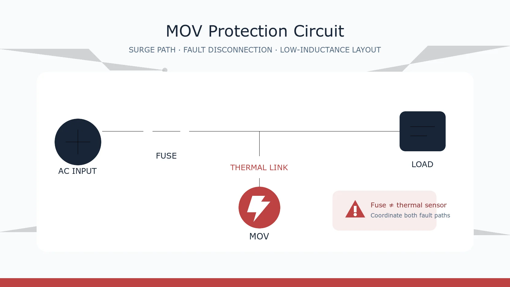
For a basic single-phase AC input, an MOV is commonly connected line-to-neutral on the protected side of an upstream fuse or circuit breaker. The MOV is therefore in parallel with the load, while the fuse is in series with the supply.
During a short surge, current flows through the MOV instead of continuing entirely into the load. The source impedance, wiring impedance and MOV current-voltage characteristic together determine the resulting voltage. The MOV does not absorb every transient without consequence, and it does not hold the voltage at one ideal fixed value.
The exact topology depends on the equipment class, earthing system, insulation design, applicable safety standard and required surge test. Line-to-earth and neutral-to-earth protection cannot be copied from a line-to-neutral example without reviewing leakage, protective-earth continuity, insulation coordination and fault-clearing behavior.
Why the Fuse Is Placed Upstream
An upstream current fuse or breaker can disconnect a sufficiently high follow current or short-circuit fault. It also protects conductors and other downstream parts against overcurrent. However, it should not automatically be described as complete thermal protection for an MOV.
A degraded MOV can draw a current that generates dangerous local heating but remains below the conventional fuse’s clearing level, especially when the fault path has significant resistance. TDK’s SIOV application guidance specifically warns that a current-type fuse may not operate in some line-to-ground fault conditions and discusses a thermally coupled fuse as one possible safety measure.
Fuse selection therefore requires more than matching the equipment’s normal current. Review:
- normal load current and inrush current;
- fuse time-current characteristic and interrupting rating;
- available fault current and upstream protection;
- the MOV’s possible end-of-life fault behavior;
- the equipment safety standard and abnormal-operation tests.
Current Fuse vs Thermal Disconnect
A current fuse responds primarily to current over time. A thermal disconnect responds to temperature at its sensing location. These are related but not interchangeable functions.
Repeated surges, temporary overvoltage, an incorrectly selected MCOV or long-duration voltage swell can increase MOV leakage and temperature. If heating progresses toward thermal runaway, a thermally coupled disconnect can isolate the MOV before the condition develops further. Integrated thermally protected varistors combine the MOV and disconnect in a controlled mechanical arrangement; some versions also provide a monitor lead.
The thermal element must be coupled to the MOV as intended by its manufacturer. Placing an unrelated thermal fuse elsewhere on the board does not guarantee the same trip behavior. After a thermal disconnect opens, the equipment may continue operating without surge protection unless the topology also disconnects the load or signals the fault.
Line-to-Line and Line-to-Ground Paths
Line-to-line or line-to-neutral protection limits differential-mode voltage. Line-to-ground and neutral-to-ground protection address common-mode paths, but they introduce different safety questions.
Before adding an MOV to protective earth, confirm:
- whether the applicable standard permits the connection;
- maximum leakage and touch-current requirements;
- creepage, clearance and insulation coordination;
- earthing-system and fault-current conditions;
- the required thermal or overcurrent disconnection method;
- whether another technology, such as a GDT or coordinated network, is required.
Do not treat a generic three-MOV diagram as universal. The correct network depends on the installation category, port type, grounding arrangement and product standard.
Why PCB Layout Changes the Residual Voltage
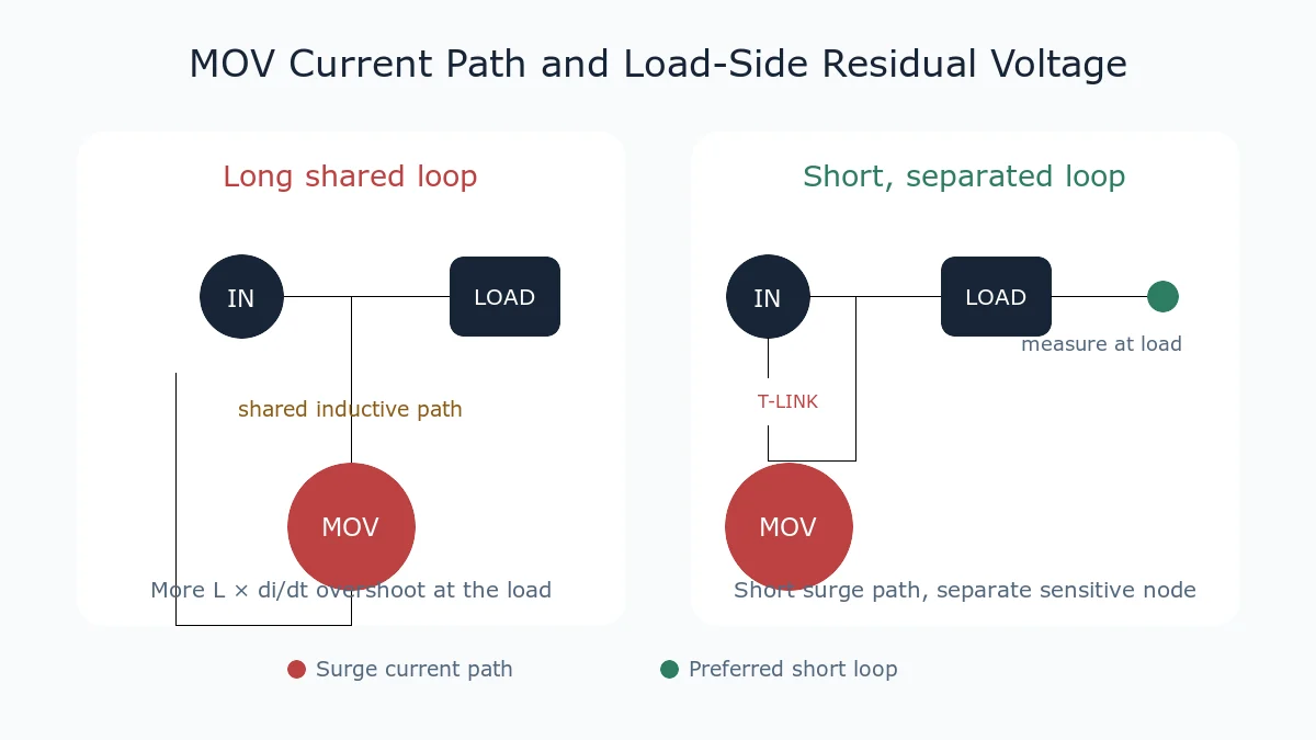
The datasheet clamping voltage is measured at the MOV under specified current and waveform conditions. The protected load can see a higher peak because the surge current also flows through lead, trace and wiring inductance.
The inductive contribution is approximately proportional to L × di/dt. A steep current front can therefore create substantial overshoot even when the conductor has very low DC resistance. Long loops, narrow detours, shared traces and remote MOV placement increase this problem.
Practical layout priorities include:
- Place the MOV close to the surge entry point.
- Keep the path from the input connector to the MOV and back short and direct.
- Avoid routing surge current through the protected circuit’s sensitive ground or supply trace.
- Use suitable conductor width, spacing and copper construction for the expected current.
- Keep voltage-probe loops short when validating the design.
- Measure at the protected load as well as at the MOV terminals.
Coordinating an MOV With Other Protection Devices
A single MOV may be appropriate for some inputs, while other systems use several protection stages. A first stage can handle more surge energy, and a second stage can provide tighter voltage limitation near sensitive electronics. Possible devices include an MOV, GDT (Gas Discharge Tube), TVS (Transient Voltage Suppression) diode, series impedance, common-mode choke or dedicated surge-protection module.
Coordination requires checking turn-on behavior, residual voltage, follow current, distance or series impedance between stages, pulse energy and failure mode. Simply placing devices in parallel does not guarantee that they will share current as intended.
Temporary Overvoltage Is Not the Same as a Surge
A short impulse and a sustained overvoltage impose different stresses. An MOV selected for a high 8/20 μs peak current may still overheat during a lower-amplitude swell lasting many cycles. Bourns notes that extended swell events can force an MOV to conduct repeatedly and accumulate heat, which is why thermal disconnection is considered in many mains applications.
Selection should therefore include the highest continuous voltage, realistic system tolerance, temporary-overvoltage scenarios and abnormal-operation requirements. Do not use only the nominal mains voltage or a one-pulse surge-current number.
Practical Review Checklist
- Is the MOV’s AC or DC MCOV above the highest continuous circuit voltage?
- Are clamping voltage, test current and waveform compatible with the load withstand limit?
- Are surge current, energy and pulse count checked under matching conditions?
- Does the upstream fuse clear the relevant fault current?
- Is a thermally coupled disconnect or thermally protected MOV required?
- Are line-to-ground connections permitted and correctly coordinated?
- Is the surge-current loop short and separated from sensitive load paths?
- Has the load-side residual voltage been measured during the required test?
- Are creepage, clearance, enclosure and flammability requirements satisfied?
- Is loss of surge protection detected or made fail-safe where necessary?
Frequently Asked Questions
How should a fuse and an MOV be coordinated?
Start with the fault conditions, not a fixed fuse part number. Check the fuse’s continuous-current margin, time-current curve, inrush tolerance and interrupting rating against the available fault current. Confirm that it clears a high-current MOV short without exceeding conductor, enclosure or equipment limits. Then assess lower-current abnormal overvoltage separately: an MOV can self-heat while branch current remains below the fuse’s opening region, so a thermally coupled disconnect or thermally protected MOV may still be required. Verify the coordination with the applicable surge and abnormal-operation tests because component ratings do not replace system validation.
Can a normal fuse protect an MOV from every overheating fault?
No. A conventional current fuse may not open during a lower-current thermal fault. The need for thermal disconnection must be reviewed against the topology, fault conditions and safety standard.
Should the MOV be installed before or after the fuse?
A common equipment-level arrangement places the MOV on the protected side of the upstream fuse, but the final answer depends on the complete power architecture and compliance requirements. Do not copy the arrangement without checking fault-current paths.
Why does moving the MOV closer to the connector help?
It shortens the high-di/dt surge-current loop and reduces inductive overshoot between the MOV and the protected load.
Conclusion
An effective MOV circuit combines electrical selection, fault disconnection and physical layout. Treat the current fuse, thermal disconnect, MOV and PCB path as coordinated parts of one protection system, then validate the residual voltage and abnormal behavior under the applicable test conditions.
Continue with MOV Clamping Voltage Explained, MOV Surge Waveforms Explained, or How to Select an MOV.












