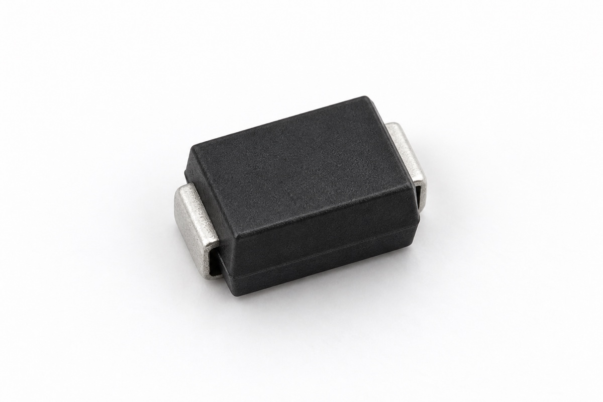
A TVS diode advertised as a 600 W, 1.5 kW, or 3 kW part does not have that capability under every transient. The peak pulse power rating is tied to a stated current waveform, pulse duration, starting temperature, and usually a non-repetitive test condition. Removing those qualifiers turns a useful datasheet value into a misleading comparison.
The engineering question has two parts. The diode must survive the applied stress, and its actual clamping voltage must keep the protected node below the system limit. A larger wattage label answers neither part by itself.
What the peak pulse power number represents
Datasheets commonly use PPP or PPPPM for peak pulse power. At a specified test point, it is associated with the peak pulse current IPP and the clamping voltage VC at that current. The current, voltage, waveform, and thermal condition must be read from the same rating set.
This is instantaneous power, not continuous dissipation and not automatically pulse energy. Energy is the time integral E = ∫v(t)i(t)dt. Multiplying peak power by pulse duration silently assumes a rectangular waveform and constant clamp voltage, which is often not the waveform in the datasheet or the circuit.
Waveform identity matters as much as the peak
An 8/20 μs current pulse and a 10/1000 μs current pulse have very different tails. Two events can share the same peak current while depositing different energy and producing different junction-temperature excursions. A rating established with one waveform therefore cannot be transferred to the other without manufacturer data that supports the conversion.
Start with the source: open-circuit voltage, source impedance, the current that will actually enter the TVS, polarity, and repetition. An IEC 61000-4-5 generator, an inductive turn-off event, load dump, and an ESD strike are not equivalent merely because each is called a surge. The IEC 61000-4-5 guide explains why generator waveform and coupling conditions belong in the system definition.
Using a peak-power-versus-pulse-width curve
Many power TVS datasheets provide a log-log curve of allowable peak pulse power versus pulse width. That curve is useful for the same device family under its stated assumptions, often a non-repetitive pulse with an initial junction or ambient temperature of 25 °C. It is not a universal scale for another die, package, waveform, or mounting condition.
Check how the datasheet defines pulse width. For a 10/1000 μs waveform, some documents define the duration at the point where current decays to 50% of its peak. A square pulse, half-sine pulse, or damped ringing waveform with the same nominal duration can produce a different thermal load. Use the manufacturer’s method or transient-thermal-impedance data, then compare the approximation with a captured current waveform.
Temperature derating changes the available margin
A headline power rating is frequently stated for a 25 °C initial condition. If the product is already hot because of ambient temperature, DC leakage, nearby components, or a preceding pulse, the available junction-temperature rise is smaller. Apply the exact datasheet’s peak-power or peak-current derating curve rather than assuming the room-temperature value remains available.
Read the temperature axis carefully: it may refer to initial junction temperature, ambient temperature, lead temperature, or another defined point. Copper pad area and PCB thermal path also matter when the datasheet states a mounting condition. The logic resembles other surge-component derating decisions, but a MOV temperature curve cannot supply numerical limits for a TVS diode.
Non-repetitive does not mean repetitive
A non-repetitive pulse rating assumes a defined thermal starting point before one event. It does not demonstrate that the same peak can be applied at any chosen frequency. Repetitive operation requires pulse energy, period, duty cycle, average dissipation, transient thermal impedance, and cooling time to be checked together.
Pulse trains can also accumulate heat even when every individual event sits below a single-pulse curve. Account for burst length, interval, production tolerance, and worst-case ambient temperature. The same boundary is discussed for another suppressor technology in the single-pulse versus repetitive-surge guide.
Why more peak power does not guarantee a safer clamp
Peak pulse power is primarily a survivability rating. Protection quality also depends on the TVS working voltage, breakdown range, dynamic resistance, clamping voltage at the relevant current, and parasitic inductance between the surge path and the diode. A high-power device can still allow too much voltage at the protected IC if the voltage family or layout is wrong.
onsemi’s discussion of peak-power ambiguity makes this distinction explicit: the largest PPP value is not necessarily the best measure of protection. Compare VC at a matched IPP and waveform, then include trace-induced overshoot. For technology-level tradeoffs, use the MLV versus TVS diode comparison; for a design decision, return to the exact ordering code.
A practical validation sequence
- Define the transient source, source impedance, current waveform, pulse duration, polarity, count, and interval.
- Confirm that VRWM, VBR, VC, IPP, and PPP belong to the same part and stated test conditions.
- Use only that series’ pulse-width curve and temperature derating; do not extrapolate across packages or technologies.
- Evaluate repetition separately with energy, duty cycle, average power, and thermal recovery.
- Measure TVS current, voltage directly across the diode, and voltage at the protected load under worst-case voltage, temperature, tolerance, and PCB layout.
FAQ
Can a 600 W TVS dissipate 600 W continuously?
No. The 600 W figure normally refers to a specified short pulse. Continuous dissipation is governed by steady-state thermal ratings, maximum junction temperature, and the actual thermal path.
Are two 3 kW TVS diodes interchangeable?
Not on wattage alone. Compare working voltage, breakdown range, clamping voltage and test current, waveform, temperature condition, package, polarity, and system layout.
Is a shorter pulse always safer?
No. A shorter event can have a much higher peak current or a sharper edge that creates inductive overshoot. Use the applicable curve and verify the real waveform.
Is P = V × I enough for TVS selection?
It is one instantaneous check. A complete decision also evaluates energy, thermal accumulation, repetition, clamp voltage, and the protected circuit’s withstand limit.
Bottom line: read a TVS peak pulse power rating as a waveform- and temperature-qualified test result. First prove that the diode survives; then prove that the voltage at the protected node remains safe.
References: onsemi AND9055/D, Ambiguity of the Peak Power Rating of TVS Devices; onsemi AND8308/D, Interpretation of Datasheet Parameters for ESD Devices; Vishay TPSMC series datasheet and pulse-power curves.