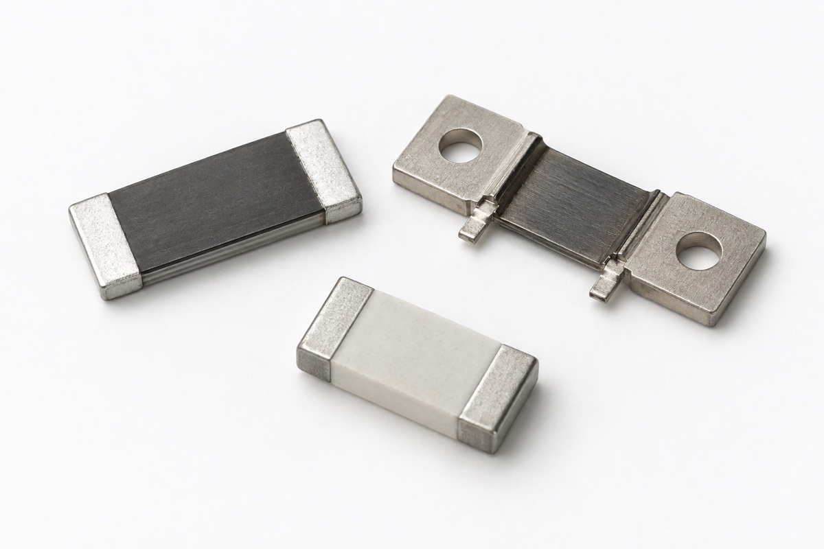
A current-sense resistor marked 1 mΩ, 5 mΩ, or 10 mΩ is normally characterized at a stated reference temperature and low measurement power. That value is not a promise that the resistance will remain identical after the part is soldered to a printed circuit board (PCB), carries load current, and reaches thermal equilibrium. Temperature coefficient of resistance (TCR), self-heating, termination behavior, solder and copper resistance, and the voltage-pickoff location can all become current-measurement error.
This means that adding initial shunt tolerance to amplifier accuracy is not a complete error budget. Start with the actual current waveform and allowable error, estimate the shunt’s operating temperature and resistance change, review the Kelvin-sense path, then add amplifier and analog-to-digital converter (ADC) errors. The complete channel must finally be checked on the production-representative PCB after its temperature has stabilized.
A current-sense resistor produces a very small signal
Ideally, shunt voltage is Vsense=I×R. A current of 10 A through 1 mΩ produces only 10 mV, while the shunt already dissipates P=I²×R=0.1 W. An unintended resistance contribution of 0.1 mΩ would therefore correspond to a 10% change in the inferred current. That scale explains why solder, copper, and sense-point placement cannot automatically be treated as negligible.
Two parts with the same nominal resistance do not necessarily deliver the same accuracy in use. Resistive alloy, terminal material, package size, rated power, TCR, thermal path, land pattern, and operating-temperature limit all matter. Initial tolerance describes one defined measurement state; it does not include every temperature and mounting effect that appears under load.
Read TCR with its reference temperature and range
TCR is commonly stated in parts per million per degree Celsius (ppm/°C). A first-order estimate is ΔR/R≈α×ΔT, where α is TCR and ΔT is the resistive element’s temperature change from the reference point. For example, a +50 ppm/°C part rising by 60 °C has an estimated resistance change of +0.3%. This calculation remains bounded by the datasheet’s definition and temperature range; a typical value is not a guaranteed maximum, and a linear approximation should not be extrapolated outside the stated region.
Element TCR and component TCR are also different concepts. Vishay’s current-sensing TCR paper distinguishes the temperature behavior of the resistive material from the finished component, which can include termination effects. In a milliohm shunt, the terminals and joining materials may not track the alloy perfectly, so the alloy’s low TCR alone does not prove the assembled component’s in-circuit drift.
Ambient temperature is not shunt temperature
Load current creates I²R dissipation and raises the resistive element above ambient. The resulting temperature depends on continuous and pulsed current, duty cycle, copper area and thickness, thermal vias, airflow, adjacent heat sources, and time to equilibrium. Two boards at the same ambient temperature can therefore produce different shunt temperatures and different current-reading errors.
The ΔT in an error budget should use the element or manufacturer-defined measurement temperature whenever possible, not simply enclosure ambient. If only surface temperature can be measured, document the location, instrument, emissivity setting or thermocouple attachment, and the stabilization criterion. Surface temperature is not automatically the internal hot spot, and a vendor temperature-rise curve applies only within its stated package and mounting conditions.
A low-current calibration does not reproduce full-load resistance
A low test current is useful for checking initial resistance because it limits self-heating. It does not reproduce the resistance reached at rated load. From cold start to thermal equilibrium, the shunt value can drift as temperature rises. If firmware is calibrated cold but used hot, the calibration coefficient can turn this thermal drift into an apparent change in current. Vishay’s shunt guidance likewise separates low-current resistance measurement from resistance after in-service stabilization.
Validation should preserve the time axis rather than recording only one final value. Cover cold start, typical equilibrium, maximum continuous current, required pulse or peak current, highest ambient, and any derated operating mode. A low average dissipation does not by itself qualify a peak-current event; pulse handling must still match the exact series, duration, repetition, and temperature conditions in its datasheet.
Solder and copper can enter the measured voltage
A two-wire voltage measurement includes drops in the current terminals, solder joints, and some PCB copper. Those extra milliohms may be insignificant for an ordinary resistor but comparable with a sub-milliohm or milliohm shunt. Copper also has a substantial temperature coefficient, so the error can change as the board warms instead of remaining as a fixed offset.
ROHM’s board-design analysis identifies solder resistance, copper-foil resistance, and voltage-detection position as influences on measured TCR performance. A four-terminal component is therefore only the starting point. If the PCB sense traces do not leave from the intended Kelvin positions, part of the high-current land or copper drop can still enter the measurement.
What Kelvin sensing fixes—and what it does not
A four-wire Kelvin connection separates the high-current terminals from high-impedance voltage-sense terminals. The paired sense traces should leave from the manufacturer’s specified locations, avoid voltage gradients in the current-carrying copper, and control loop area and coupling. The exact land pattern and pickup point belong to the selected part; a generic four-wire sketch cannot override the vendor’s layout guidance.
Kelvin routing does not remove initial tolerance, TCR, self-heating, thermoelectric voltage, amplifier offset and drift, gain error, input common-mode limits, bandwidth, ADC reference error, quantization, or timing error. High-side sensing also has to tolerate common-mode transients and input stress. In a switching converter or motor drive, the design must define whether it needs an instantaneous peak, cycle average, or filtered current because each bandwidth and sampling choice produces a different result.
Build an auditable current-sense error budget
- Define the continuous and pulsed current range, bandwidth, ambient range, allowed voltage drop, and total measurement error.
- Lock the full part number and record initial tolerance, maximum or typical TCR, reference temperature, specified range, power derating, pulse conditions, and recommended land pattern.
- Estimate I²R at the worst current, determine stabilized temperature from valid manufacturer conditions or prototype measurements, and calculate the corresponding resistance shift.
- List solder and copper contribution, Kelvin pickup location, amplifier offset/gain/drift, ADC reference and quantization, filtering, timing, and calibration residual as separate terms.
- Use an independent reference instrument to validate cold, thermally stabilized, and dynamic operation on the real PCB; repeat the check after changes to the part, layout, copper thickness, or cooling.
Use this workflow with the resistor construction and type guide, because metal-strip, foil, film, and wirewound parts have different parasitics and thermal paths. The linear versus nonlinear resistor guide explains why temperature drift does not by itself redefine the component family, while the electronic-component classification guide provides the broader terminology.
Frequently asked questions
Does a very low TCR eliminate the need for thermal testing?
No. A low TCR reduces resistance change per degree, but it does not establish the actual temperature rise or remove termination, solder, copper, amplifier, and ADC errors. The stabilized channel still needs testing at real dissipation and cooling conditions.
Does a four-terminal shunt make PCB layout unimportant?
No. The sense traces must leave from the specified Kelvin locations and avoid the main-current voltage gradient. Incorrect pads, vias, or pickup points can still include solder and copper resistance in the result.
Can one room-temperature calibration cover the full operating range?
Only when a complete error budget and validation demonstrate that it can. High-accuracy systems may need temperature compensation, multi-point calibration, or a restricted operating window, with the reference instrument, load current, and stabilization time documented.
Conclusion
Real current-sense accuracy belongs to a measurement channel, not to one TCR number. Put reference temperature, actual self-heating, component termination, solder, copper, and Kelvin pickup position into the shunt-resistance error first; then add amplifier, ADC, filtering, and calibration residuals. Validation with the exact part and real board at cold, stabilized, and dynamic corners is what shows whether a milliohm measurement meets the design requirement.
References: Vishay, Temperature Coefficient of Resistance for Current Sensing; Vishay, Power Metal Strip Shunts / Current Shunts; Bourns, Current Sense Resistors for Accurate Current Measurement; ROHM, Effects of Board Design on TCR Characteristics.