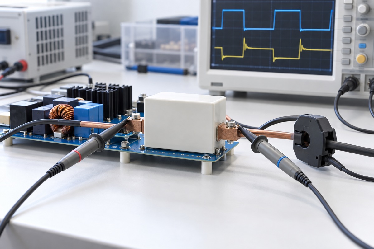
A film-capacitor dV/dt rating is often treated as a shortcut: calculate current from i = C · dV/dt, compare one number with a datasheet table, and assume pulse capability and service life are covered. The equation only relates an ideal capacitance to instantaneous current at a particular voltage slope. It does not include pulse duration, repetition, ringing, RMS loss, internal connections, hot-spot temperature, or the voltage-and-temperature conditions attached to a lifetime statement.
A defensible qualification therefore needs four separate answers. Is the instantaneous edge current acceptable? Is the repetitive or non-repetitive pulse duty covered? Will the complete waveform produce acceptable loss and temperature rise? Does the resulting operating point remain inside the selected series’ published lifetime conditions? Passing one line cannot compensate for an unknown or failed line elsewhere.
The attractive shortcut and its hidden assumptions
For an ideal capacitor, current at an instant is capacitance multiplied by the rate of terminal-voltage change. A 2 µF capacitor exposed to a 100 V/µs edge would therefore have an ideal instantaneous current of 200 A. That calculation is useful for dimensional checking and order-of-magnitude screening. It is not evidence that any particular 2 µF part is approved for 200 A.
The capacitance used in the calculation should represent the relevant operating condition and tolerance, rather than an unexamined label value. The slope should come from the voltage measured across the capacitor terminals. A gate-drive command, nominal switching frequency, or waveform measured at a distant bus node can miss local overshoot and ringing. Probe bandwidth, loop area, reference placement, and fixture inductance can also change the reported edge.
Read the rating label before comparing the number
dV/dt or dU/dt describes a local voltage slope. Ipeak or Ipkr usually describes a peak under a defined pulse rule. Irms represents the root-mean-square current of a complete waveform and is tied to dissipation. A pulse characteristic or integral may add duration information. Useful-life hours are a reliability statement under named voltage and temperature conditions. Manufacturers do not necessarily use the same symbols or acceptance criteria, so every symbol, footnote, unit, and table boundary must remain attached to the comparison.
TDK’s general technical information for film capacitors explains the relationship between voltage slope and pulse current while directing the reader back to series data for allowable values and related pulse criteria. Current KEMET R75H and Vishay MKP1848 documents likewise publish series-specific dV/dt, peak-current, RMS-current, thermal, or life information. These sources demonstrate why a general identity cannot replace the selected part’s table.
Reconstruct the waveform the capacitor actually sees
A switching-frequency value does not define a pulse. Capture the terminal-voltage extrema, the steepest local rise and fall, overshoot, ringing frequency and decay, pulse width, repetition rate, and duty cycle. Include startup, shutdown, load steps, current-limit operation, and credible fault clearing. If polarity reverses or several operating modes create different pulse families, record each family separately.
The measurement should be taken as close as practical to the capacitor terminals with a controlled probe loop. Record probe type, bandwidth limit, sampling rate, attenuation, reference point, and the operating corner. A repeatable waveform with known measurement limits is more useful than the largest-looking screenshot. An unresolved probing artifact should remain an uncertainty, not become a part rating.
Turn slope into current without turning the calculation into approval
Use the measured local slope and a stated capacitance assumption to calculate the instantaneous current estimate. Then compare the result only with the exact series’ dV/dt and peak-current rules. If a datasheet permits a dV/dt adjustment at a lower working voltage, apply only that series’ rule and only within its stated range. It is not a universal linear scaling law for polypropylene or film capacitors.
The calculation still says nothing directly about the metallization, sprayed end contacts, leads, busbars, dielectric, or accumulated pulse heating. A current estimate below one table value is an input to the next checks, not a complete pass. This distinction is especially important during substitution, when two capacitors can share capacitance, voltage, and package dimensions while using different internal constructions and pulse criteria.
Add duration and repetition—the dimensions the edge omits
Pulse width, repetition frequency, duty cycle, polarity sequence, ringing cycles, and cooling interval all influence electrical and thermal stress. A rare startup edge and a continuous switching pulse train should not be classified by the same peak number. If the document defines a pulse integral, characteristic, or separate repetitive and non-repetitive current, that condition must be evaluated rather than replaced by the ideal edge equation.
KEMET C4AK provides a useful product-bound example: the series document limits 1.5 × IPKR to a maximum of 1,000 non-repetitive events over life. That statement cannot be converted into a continuous switching allowance, and it does not apply to another family. When a candidate datasheet provides only a non-repetitive peak but the application creates a persistent pulse train, the honest result is “supplier clarification required.”
Build the thermal path from Irms to hot spot
Calculate Irms from the entire periodic current waveform, including material harmonic or ringing content. Peak current is not a substitute. Equivalent series resistance and dielectric loss can depend on frequency, temperature, and construction, while heat rejection depends on case geometry, lead or busbar conduction, PCB copper, spacing, airflow, and nearby heat sources.
Vishay’s technical note on power dissipation for polypropylene DC-link capacitors provides a method that links ripple current, loss, and temperature rise, with an MKP1848 worked example. The method is valuable for structuring a review; the numerical result of that example is not proof for a different series or mounting arrangement. At the prototype stage, stabilize the worst relevant input, load, switching, cooling, and ambient condition, then measure the case or manufacturer-defined hot-spot-related temperature with the test setup documented.
Why a dV/dt pass can still miss the lifetime target
Lifetime hours are meaningful only beside the product series, applied-voltage definition, ambient or hot-spot temperature, and failure criterion. R75H, C4AK, and MKP1848 publish different conditioned statements. The editorial lesson is not that one family is universally better; it is that the conditions control the meaning. Hour figures from separate documents cannot be combined into a generic curve, and a dV/dt margin does not create a fixed lifetime multiplier.
The application mission profile adds operating-time fractions, light and full load, startup and shutdown, fault handling, ambient cycling, and component tolerances. Repetitive current may raise the hot spot enough to invalidate an otherwise acceptable voltage condition. Conversely, a low-average-duty event can remain thermally mild while violating a peak-current, pulse-integral, or connection limit. The electrical and thermal paths must therefore converge before life is assessed.
An eight-step design-review workflow
- Lock the manufacturer, series, part number, capacitance and tolerance, voltage rating, construction, and document revision.
- Measure worst-case terminal voltage and record extrema, local dV/dt, overshoot, ringing, width, repetition, and duty.
- State the capacitance assumption and calculate instantaneous current with units and uncertainty.
- Compare only against that series’ dV/dt, Ipeak/Ipkr, pulse-integral, and repetitive or non-repetitive rules.
- Calculate Irms from the complete cycle and apply the series’ frequency-dependent loss method or data.
- Document ambient, airflow, spacing, mounting, PCB or busbar conduction, and steady-state case or hot-spot-related temperature.
- Check working voltage, maximum temperature, and lifetime condition together; no dV/dt pass can override another failure.
- Cover supply, load, tolerance, switching, startup, fault, and environmental corners; request written supplier guidance outside published limits.
A comparison worksheet for substitutions
| Review line | Evidence to retain | Unsafe shortcut |
|---|---|---|
| Identity | Part, revision, C/tolerance, rated and applied voltage | Compare package and nominal µF only |
| Instantaneous pulse | Terminal dV/dt, Ipeak/Ipkr, width, polarity, integral or characteristic | Treat i = C · dV/dt as approval |
| Repetition and heat | Frequency, duty, Irms, loss method, ambient, mounting and cooling | Use peak current as a thermal rating |
| Life | Series voltage, ambient/hot spot, hours and failure criterion | Call catalog hours equipment life |
Use pass, fail, or supplier clarification for every operating corner. “Unknown” is a legitimate engineering result. It identifies the next measurement or question and prevents a missing repetitive-pulse or thermal rule from being silently interpreted as approval.
When bench evidence or manufacturer review is mandatory
Escalate when the waveform lies outside the published pulse family; ringing or interconnect parasitics dominate terminal slope; parallel parts may share dynamic current unevenly; the available thermal model does not represent the assembly; or the required mission life exceeds the published voltage-temperature envelope. A validation plan should name the measurement points, probes and bandwidth, sample count, warm-up, input and load corners, ambient condition, and pass criteria. Calculations and simulations must not be reported as tests that UBAEC has performed.
FAQ
Is dV/dt the same as peak-current rating?
They can be related for a stated capacitance and waveform, but the datasheet may impose separate peak-current, pulse-duration, integral, voltage, and construction limits. Preserve both fields and their footnotes.
Can dV/dt be increased in proportion when working voltage is lower?
Only when the selected series document explicitly provides that adjustment and its valid range. A rule from R75H, MKP1848, or another family must not become a universal film-capacitor formula.
Why calculate Irms when Ipeak is below the limit?
Ipeak does not represent cycle-average dissipation. High repetition, several ripple frequencies, or a weak thermal path can produce excessive hot-spot temperature even when each peak is below its limit.
Where should the oscilloscope measure dV/dt?
Measure across the capacitor terminals with a small, documented probe loop whenever practical. Record bandwidth, probe type, sampling, reference, and the operating corner instead of using a controller command as the capacitor waveform.
Practical conclusion
dV/dt is an entry point for film-capacitor pulse review, not a lifetime calculator. Convert the measured terminal slope into an instantaneous-current estimate, then apply the exact series’ peak and repetitive-pulse rules. Independently close the Irms, frequency-dependent loss, mounting, cooling, and hot-spot checks. Only after those results are mapped to the manufacturer’s voltage-temperature-life statement is there enough evidence to accept an application or substitution.
Continue with Electronic Component Types and Functions, Electronic Component Abbreviations and Datasheet Terms, the Component Center, and the UBAEC contact page for waveform-based questions.
References
- KEMET R75H Metallized Polypropylene Film Capacitors
- KEMET C4AK DC-Link Metallized Polypropylene Film Capacitors
- Vishay MKP1848 DC-Link Metallized Polypropylene Film Capacitors
- Vishay, Calculation and Interpretation of Power Dissipation for Polypropylene Film DC-Link Capacitors
- TDK Electronics, Film Capacitors — General Technical Information