

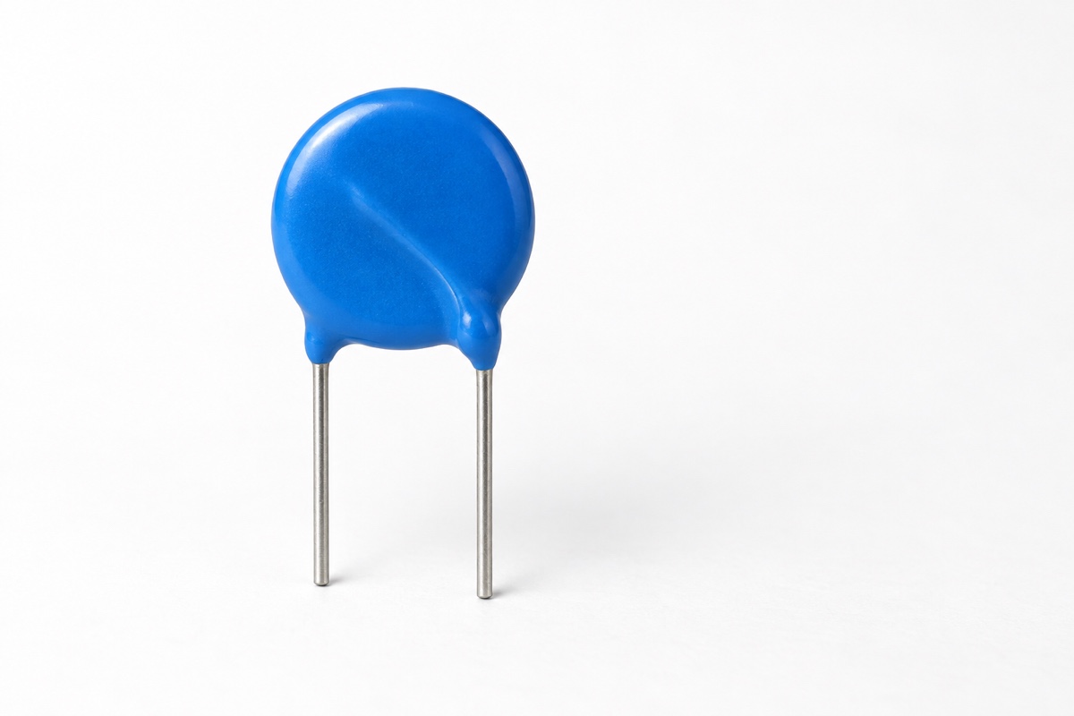
A leakage-current value in an MOV datasheet applies to one defined test point. A result measured at 25°C and a specified DC bias cannot be carried unchanged into a hot enclosure, an AC power calculation, or an end-of-life threshold. The current belongs to a strongly nonlinear voltage-current characteristic, so even a modest change in voltage or temperature may move the device to a very different operating point.
Start by stating the decision the number must support. Incoming inspection needs a repeatable component test against a published maximum. A standby-power calculation needs the real-loss component under the actual waveform. Condition monitoring needs a baseline, controlled temperature, and a part-specific trend limit. In every case, the test definition has to match the system voltage, local temperature, and service history being assessed.
What the instrument is actually measuring
After a DC voltage step, the displayed current can include steady conduction through the MOV, charging current from the device and cable capacitance, leakage across the fixture insulation, instrument input offset, and environmental noise. A useful bookkeeping expression is Imeas(t) = IMOV(V,T,state) + Ceq·dV/dt + Ifixture + Ioffset/noise. This is an error-budget model rather than a fitted equation for a particular MOV. The displayed value approaches the specified steady leakage only after the transient has settled and the test-system background has been shown to be small enough.
The term leakage current also changes meaning between documents. A component datasheet may report steady current under DC bias. An AC test may report total RMS current, including a displacement-current component. An equipment safety test may measure current in a path to protective earth or an accessible part. Those measurements use different circuits and answer different questions, so a report should name the measurand rather than list only a number in microamperes.
Locate the leakage-current point on the V-I curve
A metal-oxide varistor (MOV) remains highly resistive during normal operation, but it is not an ideal open circuit. In its equivalent-circuit discussion, TDK describes a low-current leakage region below roughly 10−4 A in which the intergranular resistance has a strong influence on behavior. That boundary belongs to the explanatory model in the cited technical document; it is not a universal maximum-leakage specification for every MOV family.
Leakage current must also be kept separate from varistor voltage and clamping voltage. A V1mA test forces 1 mA DC through the device and measures the resulting voltage; some low-voltage or small devices define another reference point, such as V0.1mA. A leakage test normally applies a specified AC or DC voltage in the continuous operating region and measures current. Clamping voltage is measured at a much higher pulse current under a stated waveform. These tests use different controlled quantities and answer different design questions.
A usable leakage specification needs more than a current value
Applied voltage and AC or DC basis
The first missing detail is often the bias voltage. Leakage may be stated at maximum continuous operating voltage (MCOV), at a lower bias, or at a separate test voltage defined in a footnote. An AC entry should identify whether voltage is expressed as RMS and at what frequency; a DC entry may also require a polarity and ripple definition. An AC rating cannot be converted into a guaranteed DC leakage value with a simple square-root-of-two calculation.
Temperature and thermal state
Many tables use 25°C, while the MOV on a working board may sit beside a bridge rectifier, power resistor, relay, or heat sink. Temperature matters most in the low-current region. TDK’s technical discussion shows that varistor voltage has a negative temperature coefficient at low currents; viewed at a fixed applied voltage, this means leakage tends to rise as temperature increases. A room-temperature reading is not a substitute for a hot-enclosure limit.
Settling time and measurement window
Immediately after DC voltage is applied, the instrument measures charging current from the MOV and the fixture as well as conduction through the device. The reading approaches steady state only after that capacitive component decays. Comparisons made with different dwell times are not comparable. Where a manufacturer does not publish a settling time, the internal test method should still fix the voltage ramp, dwell period, sampling window, and criterion for a stable reading.
Typical, maximum, and post-stress limits
A typical value describes representative behavior; it does not guarantee that every shipped unit will remain below that value. A maximum value can serve as a procurement boundary, but only under its stated conditions. Production screening and qualification tests may use a different voltage, temperature, duration, or allowable shift. The word “negligible,” without a numerical limit and test definition, should not be converted into a guaranteed power budget.
Device history matters as well. Initial leakage, thermally stabilized leakage, and leakage after surge, temporary-overvoltage, damp-heat, or endurance exposure are different measurements. A post-stress result should be compared with a baseline obtained by the same method and with the acceptance limit defined before testing. A microampere-scale reading by itself does not prove that varistor voltage, clamping behavior, insulation, and thermal stability are unchanged.
AC current is not necessarily resistive leakage
An MOV has capacitance as well as a nonlinear resistance, and its instantaneous displacement current follows iC = C·dv/dt. The familiar IC,RMS ≈ 2πfCVRMS form is appropriate only as an approximation for a nearly sinusoidal, single-frequency voltage with reasonably stable capacitance. Frequency, harmonics, voltage slew rate, capacitance, and instrument bandwidth can therefore change the measured AC current even when the material condition of the MOV has not changed.
After the charging transient has decayed, a DC measurement can approach the steady conduction current. Under AC, displacement current remains present on every cycle. Treating total RMS current as degradation can create a false alarm, while multiplying that current by RMS voltage can overstate real power when a substantial part of the current is reactive. A power analyzer or phase-sensitive measurement may be needed when actual loss is the design constraint.
A datasheet example shows why voltage margin matters
TDK’s general SIOV document uses the S14K14 tolerance band to illustrate the relationship. At that part’s specified 18 VDC maximum continuous operating voltage, the plotted band corresponds to leakage from approximately 6 μA to 200 μA, depending on where a unit lies within the allowed V-I tolerance. At 10 VDC, the document gives a maximum possible leakage of about 2 μA. The figures belong to that named part and curve, not to MOVs in general.
The figures also show why a linear extrapolation is unreliable. A moderate reduction in applied voltage can reduce current by far more than the same percentage, while production tolerance can produce a wide current range at one voltage. Use the applicable table or worst-case V-I boundary instead of extrapolating from nominal varistor voltage or from one room-temperature sample.
A repeatable bench method
Begin with the complete ordering code and the exact manufacturer table, note, or curve. Record the applied voltage, AC or DC basis, temperature, dwell time, and whether the published number is typical or maximum. For DC work, a source-measure unit with adequate voltage capability, microampere or nanoampere resolution, and programmable current compliance is often appropriate. An equivalent controlled high-voltage source and current-measurement arrangement can also work. A handheld multimeter in resistance mode usually cannot reproduce the datasheet operating point.
At microampere levels, the fixture can dominate the result. Surface contamination, humidity, cable leakage, electrostatic coupling, and instrument noise all create currents that do not belong to the MOV. Shielding and guarding address different problems: a conductive shield reduces electrostatic pickup, while a driven guard holds insulation near the high-impedance node at nearly the same potential so that leakage is diverted away from the ammeter input. The guard terminal is instrument-driven and must be connected according to the instrument manual; it is not a substitute name for protective earth.
Measure the background of the instrument, cables, and empty fixture at the actual test voltage before fitting the device. Watch the background as a function of time rather than assuming that a zero check at 0 V represents the high-voltage condition. For the device measurement, use a fixed voltage ramp and dwell time, then record an average, range, or time series over a defined stable window. The report should include current range, integration time, resolution, noise floor, temperature, humidity, and fixture condition. A reading below the demonstrated system capability is reported as “less than” a stated detection limit, not as zero.
Lot comparisons and before-and-after stress measurements require the same polarity, fixture, lead arrangement, thermal state, voltage ramp, dwell time, and discharge sequence. They also need a representative sample plan rather than one convenient part. Testing line-connected MOVs adds a separate safety problem: isolation, current limiting, emergency shutdown, and discharge of stored energy belong in the procedure. An unknown device should never be connected directly to an uncontrolled high-voltage source.
Set the acceptance rule before measuring
When a datasheet provides a maximum leakage value Ilimit, a display just below that limit is not automatically a comfortable pass. The decision should account for background current, repeatability, temperature stability, calibration status, and the uncertainty method used by the laboratory. A conservative rule such as Imeas + U ≤ Ilimit may be appropriate for a critical inspection, provided that U and its confidence basis are defined in the procedure. It is an example of guard-banding, not a universal acceptance formula.
Background correction also needs discipline. Subtraction is defensible only when the empty-fixture measurement uses the same polarity, voltage, dwell time, range, and environment, and when that background is stable and repeatable. Otherwise, improve insulation, cleaning, shielding, and guarding until the background is well below the decision region. A lot report should retain the worst individual result and the distribution; an average alone can hide a small number of parts close to the limit.
Use a protocol that matches the engineering decision
| Purpose | Measurement focus and conclusion |
|---|---|
| Incoming or outgoing inspection | Measure the standalone part at the manufacturer’s specified voltage. Fix AC/DC basis, temperature, dwell time, range, and maximum-value definition. The result applies only to that specification condition. |
| Post-stress reliability | Compare absolute value and shift with a same-method baseline. Fix stress exposure, recovery time, and retest temperature. One room-temperature reading cannot characterize every form of damage. |
| Standby power | Measure real power or the in-phase current component under the actual voltage waveform, frequency, and local temperature. Total AC RMS current is not automatically real loss. |
| RCD or insulation monitoring | Measure current in the defined earth or residual-current path. Record MOV location, parallel branches, frequency content, and operating state. Board-level total current cannot be assigned to one MOV without separation. |
| Online condition monitoring | Trend leakage and temperature at controlled voltage and sampling time. Define a baseline and alarm logic, then correlate with V1mA, temperature rise, appearance, or other relevant checks. |
Using leakage-current data at system level
For standby-power analysis, identify which current component produces real loss. With DC, voltage multiplied by stabilized current can be a useful device-loss estimate when the definitions match. With AC, RMS voltage multiplied by total RMS current is apparent power, not necessarily real power, when capacitance or waveform distortion is significant. The resulting loss must then be checked against local cooling and the highest operating temperature, not only against a room-temperature electrical limit.
Connection position determines how leakage affects protection and monitoring. Current through a line-to-earth MOV contributes to the equipment’s earth-leakage budget and may add to currents from EMI capacitors, filters, and sensing networks. A line-to-line MOV does not enter a protective-earth current calculation in the same way. Residual current device (RCD) coordination and insulation monitoring therefore have to be evaluated from the complete circuit, including the number and location of protective branches.
Leakage can support condition monitoring, but a universal microampere alarm is rarely defensible. Establish a baseline at controlled voltage and temperature, track the trend, and define the alarm against a part-specific upper limit or non-recovering shift. Varistor voltage, physical condition, temperature rise, insulation, and—where relevant—clamping behavior should be checked alongside leakage. No single measurement proves the health of a surge-protection path.
Measurements on an assembled board need separate treatment. A bridge rectifier, EMI capacitors, bleeder resistors, indicators, PCB contamination, and other surge branches can all contribute current or change the waveform actually applied to the MOV. Unless the MOV branch can be isolated or the other paths can be removed with a traceable method, the result describes the node or equipment—not the standalone component value listed in the datasheet.
Common mistakes in datasheet reviews
- Copying a microampere value without its voltage, temperature, and dwell time.
- Treating a typical value or the word “negligible” as a guaranteed maximum.
- Calling all AC current resistive leakage while ignoring capacitance and frequency.
- Using leakage current to infer V1mA, or using V1mA to predict continuous-region leakage.
- Testing only new parts at room temperature and ignoring hot operation or post-stress behavior.
Frequently asked questions
Can leakage current be used to calculate varistor voltage?
Not as a direct conversion. Leakage testing applies voltage and measures current, while a V1mA or V0.1mA test forces the stated reference current and measures voltage. A relationship can be discussed only when the manufacturer supplies a suitable V-I curve or tolerance band at matching temperature and polarity. Even then, a curve estimate should not be promoted to a guaranteed production limit.
Does higher leakage at temperature prove that the MOV is damaged?
No. Increased leakage can be a normal, reversible consequence of the MOV’s low-current temperature dependence. Bring the device back to the specified temperature and repeat the measurement with the same voltage and dwell time. Damage is supported by an exceeded limit, a non-recovering shift, or corroborating changes in other parameters—not by comparison with a room-temperature typical value.
What should I do if the datasheet gives no maximum leakage current?
Do not turn a typical value into a contractual limit. Ask the manufacturer for a maximum or distribution at the required voltage and temperature, select a better-specified series, or validate representative units under the equipment’s worst credible conditions. If leakage affects safety, regulated standby power, or a fault threshold, include a measurable upper limit and test method in the technical agreement.
Can an in-circuit reading be compared directly with the datasheet?
Usually not. Other components and PCB leakage may share the measurement path, and the voltage waveform across the MOV may differ from the source setting. Draw the actual test loop and determine whether the MOV branch can be isolated. If it cannot, label the result as node or equipment current and use standalone samples or a validated de-embedding method for the component-level comparison.
Engineering conclusion
A defensible MOV leakage-current result includes the applied voltage, AC or DC basis, frequency, temperature, settling time, device tolerance, and statistical status. It also separates steady conduction from capacitive transients, component current from test-system background, and standalone component limits from equipment-level behavior. With those definitions in place, the measurement can cover the highest continuous system voltage, the hottest credible location, and the component state after relevant service stress.
Related reading includes Datasheet Parameters and Test Conditions, MOV MCOV Selection, and What Is V1mA?. When requesting a part-specific acceptance method through the UBAEC contact page, include the circuit voltage, temperature, connection position, and required limit. Those details are more useful than a generic request for a low-leakage MOV.












