

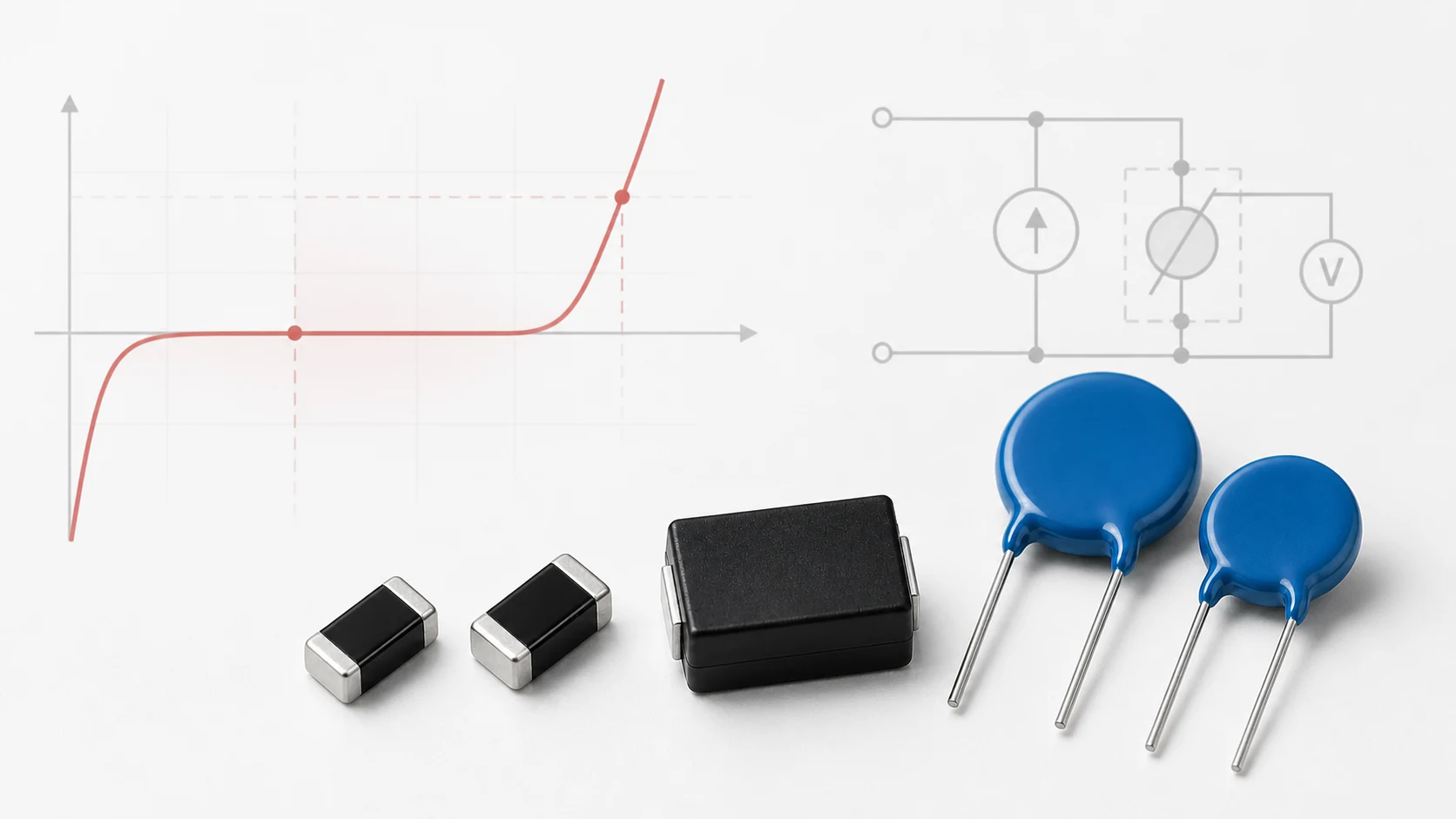
V1mA is the voltage measured across a varistor while a direct-current test current of 1 milliampere flows through it. It is a reference point on the device’s nonlinear voltage-current curve. Manufacturers use it to classify the varistor and specify a production tolerance.
V1mA is commonly called the varistor voltage at 1 mA. Datasheets may use symbols such as VV, VNOM, V1mA or VBR. The exact symbol is less important than the definition and test condition printed in the datasheet.
V1mA is not the maximum continuous operating voltage and it is not the clamping voltage during a surge. Confusing these three values can cause excessive leakage during normal operation or inadequate protection during a transient.
What Does the “1 mA” Mean?
An MOV (Metal-Oxide Varistor) does not switch at one perfectly sharp voltage. Its current rises continuously and nonlinearly as the applied voltage increases. A manufacturer therefore needs a repeatable point on that curve for production measurement.
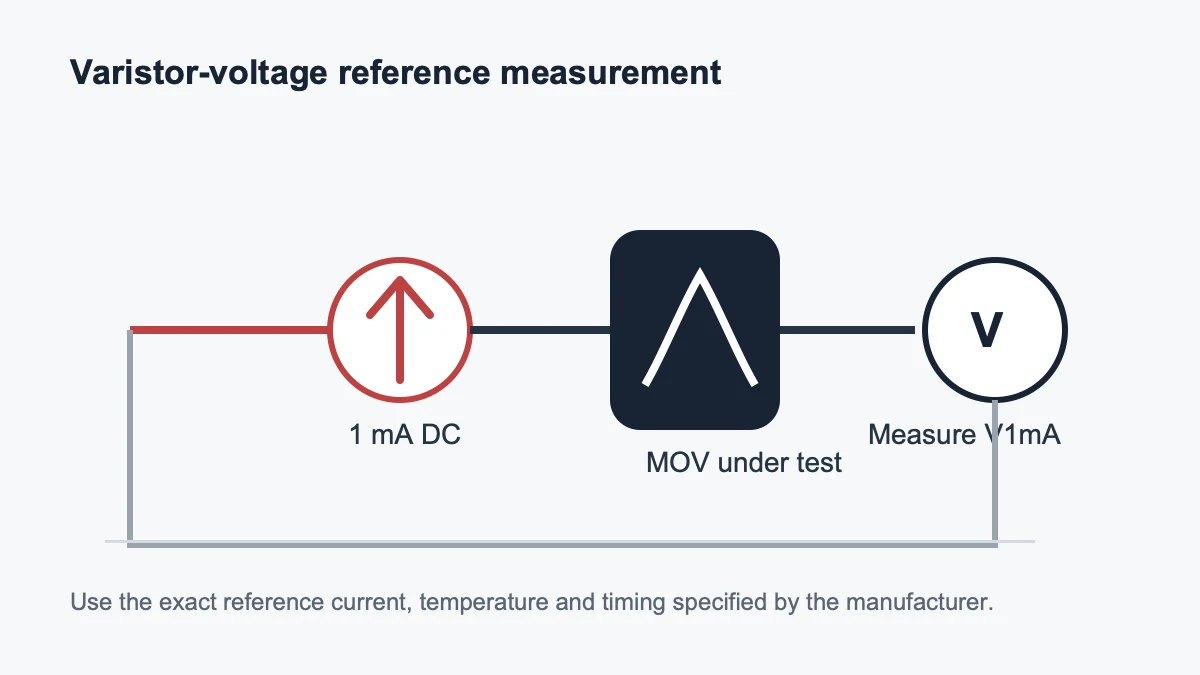
For many radial disc MOV families, that point is defined at 1 mA DC. If a datasheet lists a nominal varistor voltage of 470 V at 1 mA, the device develops approximately 470 V while the specified 1 mA test current flows under the stated conditions.
The measurement current is part of the specification. Some small MLVs (Multilayer Varistors), low-voltage suppressors or special series may use 0.1 mA, 10 mA or another current. A voltage measured at 0.1 mA cannot be treated as the same value as a voltage measured at 1 mA.
How V1mA Is Measured
A basic measurement uses a current-limited DC source or a source-measure unit. The instrument raises the voltage until the specified current flows, then records the voltage across the varistor. The actual production method may also define polarity, ramp rate, measurement time, current accuracy, temperature and preconditioning.
- Connect the varistor to a current-limited measurement source.
- Increase the voltage under controlled conditions.
- Stop at the datasheet’s reference current.
- Measure the voltage across the component.
- Compare the result with the specified minimum and maximum limits.
The test should be short enough to avoid significant self-heating. Use the manufacturer procedure when the result is being used for incoming inspection, reliability qualification or failure analysis.
How Varistor-Voltage Tolerance Works
A varistor voltage is normally specified as a range or as a nominal value with tolerance. If the nominal value is 470 V with a ±10% tolerance, the theoretical limits are 423 V and 517 V. A manufacturer may instead publish rounded or series-specific limits.
| Item | Example | Meaning |
|---|---|---|
| Nominal V1mA | 470 V | Reference classification point |
| Tolerance | ±10% | Permitted production window at the specified test current |
| Lower limit | 423 V | Must still avoid excessive conduction at the highest normal voltage |
| Upper limit | 517 V | Must still provide an acceptable protection level during a surge |
Selection must consider both ends of the tolerance band. The lowest-voltage device is usually the leakage and continuous-stress case. The highest-voltage device is usually the clamping and protected-load withstand case.
V1mA vs Maximum Continuous Operating Voltage
The maximum continuous operating voltage, often listed separately for AC RMS and DC, is the highest voltage intended to remain across the MOV under stated conditions. It is lower than V1mA because the MOV should normally remain in its high-resistance region.
Do not select an MOV by matching the nominal supply directly to V1mA. Start with the highest continuous circuit voltage, including tolerance and abnormal operating conditions, then confirm the manufacturer’s permitted AC or DC operating voltage.
V1mA vs Clamping Voltage
V1mA is measured at a small reference current. Clamping voltage is measured at a much larger pulse current, normally with a specified waveform such as 8/20 μs. Because the MOV has finite dynamic resistance, its voltage rises as surge current rises.
For example, a device classified near 470 V at 1 mA may have a maximum clamping voltage hundreds of volts higher at tens or hundreds of amperes. The correct value must be read from the datasheet table or maximum voltage-current curve at the relevant current.
Why V1mA Is Used in Reliability Tests
A change in varistor voltage can indicate electrical or thermal stress. Datasheets and qualification methods may measure V1mA before and after surge, temperature, humidity or endurance tests, then limit the permitted percentage change.
A stable V1mA result alone does not prove that the device is undamaged. Leakage current, appearance, insulation, clamping behavior and other requirements may also need to pass. For field failures, compare several parameters rather than relying on one resistance reading. When evaluating the leakage-current result, read it together with the applied voltage, temperature, timing and typical-or-maximum status described in this MOV leakage-current datasheet guide.
Can a Multimeter Measure V1mA?
Usually not directly. A normal resistance or diode-test mode often cannot supply the voltage required to reach the reference current of a mains-rated MOV. A suitable high-voltage, current-limited source and safe measurement procedure are required.
Do not connect an unknown MOV directly to an uncontrolled high-voltage supply. Stored energy, exposed conductors and component failure can create shock and fragment hazards.
Common Reading Mistakes
- Assuming every varistor uses a 1 mA reference current.
- Treating V1mA as the maximum continuous operating voltage.
- Treating V1mA as the surge clamping voltage.
- Ignoring the tolerance band and using only the nominal value.
- Comparing values measured at different currents or temperatures.
- Using a part marking without checking the series datasheet.
- Using a post-stress V1mA check as the only reliability criterion.
Practical Datasheet Checklist
- Find the exact symbol used for varistor voltage.
- Confirm the measurement current and whether it is DC.
- Record the minimum, nominal and maximum values.
- Check the AC and DC continuous operating-voltage limits separately.
- Check maximum clamping voltage at the stated pulse current.
- Read the voltage-current curve and temperature conditions.
- For qualification, confirm the permitted post-test voltage shift and other pass criteria.
Frequently Asked Questions
Does 471 mean the MOV has a V1mA of exactly 470 V?
Not necessarily. A marking such as 471 commonly indicates a 470-class varistor voltage, but the exact range, test current and marking system are series-specific. Check the manufacturer’s datasheet.
Is a higher V1mA always safer?
No. A higher value may reduce normal leakage but also increase the residual voltage seen by the protected circuit. Selection requires a voltage window between the highest normal voltage and the lowest damage threshold.
Can V1mA be used to compare MOV size?
No. Devices of different sizes can share the same V1mA while having very different surge current, energy, power and endurance ratings.
Conclusion
V1mA is a controlled reference measurement, not an operating limit and not a surge-clamping result. Read it with its test current, tolerance, temperature and series definition. Then use continuous voltage, maximum clamping voltage, surge current, energy and endurance data to complete the selection.
Continue with MOV Key Parameters Explained, How to Select an MOV, or send a project question through Ask UBAEC.












