
UBAEC | Electronic Components & Application Insights
  • Components
  • Applications
  • Wiki
    • Submit a Technical Question
  • Technical Topics
  • Industry News
No Result
View All Result
  • MOV
  • MLV Knowledge Map
UBAEC | Electronic Components & Application Insights
  • Components
  • Applications
  • Wiki
    • Submit a Technical Question
  • Technical Topics
  • Industry News
No Result
View All Result
UBAEC | Electronic Components & Application Insights

Automotive Load Dump Protection: Selecting MOV, TVS and MLV Devices

Viki by Viki
2026-09-07
in Application Notes
A A
Share on FacebookShare on Twitter

Load dump is a high-energy automotive transient that can occur when a battery is disconnected while the alternator is supplying current. The alternator and regulator response can create a voltage rise much longer than ESD or a microsecond-scale switching spike.
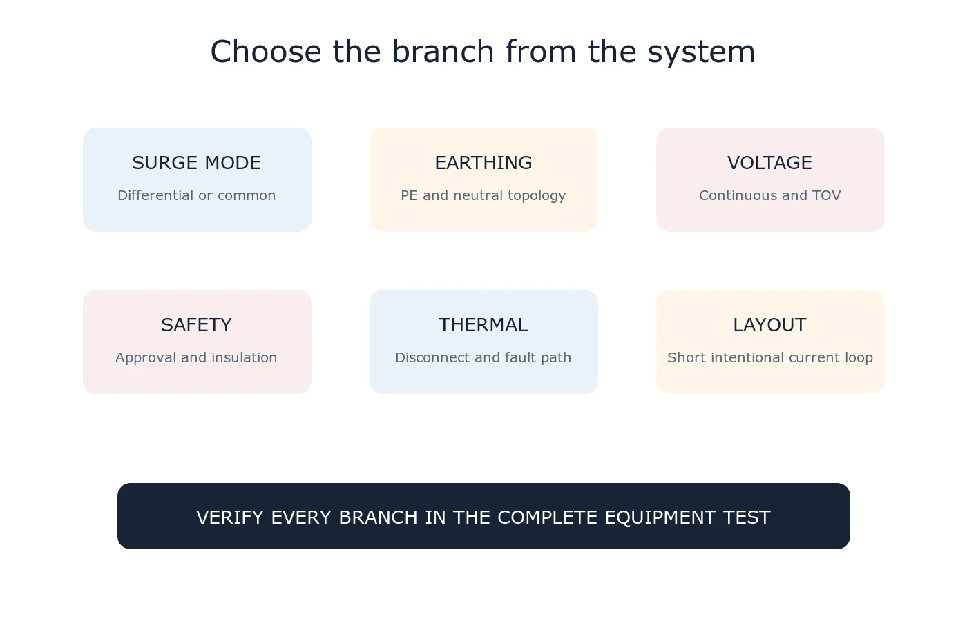
Checklist for identifying surge coupling mode, current path and protection location
Start with the specified vehicle pulse and module connection rather than selecting from nominal battery voltage alone.

Load Dump Is Not One Universal Pulse

The test voltage, source resistance, duration and suppression condition depend on the vehicle architecture and applicable standard or OEM specification. A 12 V system, 24 V system and centrally suppressed alternator can produce different requirements.

Choose the Protection Technology by Location

High-power TVS diodes are widely used at module power inputs because they provide a controlled breakdown characteristic. MOVs can offer useful energy capability and bidirectional behavior in appropriate voltage ranges. MLVs are compact and valuable for lower-energy transients and ESD near sensitive signal or low-voltage power nodes. These names do not make the devices interchangeable.

Define the Voltage Window

The suppressor must remain off during jump start, charging tolerance and other permitted continuous conditions, yet clamp below the module’s damage threshold during the specified transient. Check the maximum value over temperature and tolerance, not only the nominal breakdown or V1mA.

Account for Source Resistance and Pulse Duration

Peak current depends on the difference between the source voltage and clamp voltage divided by the defined source resistance. Power and energy then depend on the time-domain waveform. An 8/20 microsecond surge-current rating alone cannot represent a load-dump pulse lasting tens or hundreds of milliseconds.

Coordinate the Complete Input

The protection device works with the connector, harness, reverse-polarity element, fuse, EMI filter, input capacitor and regulator. Trace inductance creates overshoot, while the input capacitor changes current sharing. Bench testing should use representative wiring and operating states.

Design Checklist

  • Applicable ISO, regional or OEM pulse definition.
  • 12 V or 24 V architecture and central suppression.
  • Maximum continuous, jump-start and reverse-polarity conditions.
  • Source voltage, resistance, duration and pulse count.
  • Suppressor maximum clamp voltage over temperature.
  • Peak power, pulse energy and cooling interval.
  • Protected IC and capacitor absolute maximum ratings.
  • AEC-Q qualification and change-control requirements where applicable.

Related Guides

  • MOV vs TVS Diode
  • MOV Clamping Voltage
  • MOV Surge Waveforms

Reference

  • Littelfuse — TVS Diodes and Automotive Load Dump Standards

For a private review, send the vehicle voltage, pulse definition, source resistance, module limits and schematic through Ask UBAEC.

Tags: AutomotiveISO 16750-2Load DumpMLVMOVTVS Diode
Next Post
MLV engineering knowledge map linking mechanism, parameters, selection, reliability, applications and evidence

MLV Terminology and Product Boundaries

Conceptual MLV operating regions from normal leakage through transient conduction to post-pulse recovery

How Multilayer Varistors Work

  • Trending
  • Comments
  • Latest
Blue radial metal-oxide varistors used for transient overvoltage protection

What Is a Varistor? MOV Basics and Key Parameters

2026-09-07
Populated electronic circuit board on a laboratory test bench

What Are Electronic Components? Common Types, Functions and Selection Basics

2026-09-07
Conceptual MLV operating regions from normal leakage through transient conduction to post-pulse recovery

How Multilayer Varistors Work

2026-09-07
IEC 61000-4-5 combination-wave surge test chain from generator through coupling network to equipment under test

IEC 61000-4-5 Surge Test Explained: Waveforms, Coupling and Interpretation

2026-08-10
Populated electronic circuit board on a laboratory test bench

What Are Electronic Components? Common Types, Functions and Selection Basics

1
Oscilloscope probes measuring surge residual voltage between the protected node and local return after an MOV

Why Do MOV Leads and PCB Traces Increase Residual Voltage?

1
Blue radial metal-oxide varistors used for transient overvoltage protection

What Is a Varistor? MOV Basics and Key Parameters

0
Multilayer chip varistors and molded surface-mount MOV packages used for circuit protection

What Is an SMD MOV? Types, Parameters and Applications

0
GDT devices with a surge generator and oscilloscope in a circuit-protection test setup

Why Can a GDT Keep Conducting After a Surge?

2026-09-16
Single two-terminal MLCC in a measurement fixture with a completed thermal-history backdrop and a conceptual slow downward time trend

MLCC Aging and De-Aging: Capacitance After Reflow and Referee Time

2026-09-15
Disc MOV on a test fixture with a thermal image and a time-voltage withstand curve

How to Read MOV TOV Data: Temporary Withstand Is Not MCOV

2026-09-14
Three-lead thermally protected MOV connected to a status LED and optocoupler test board

How Should the Third Lead of a Thermally Protected MOV Be Wired?

2026-09-13

Need help selecting a component?

Share the operating voltage, package, surge or ESD conditions. We will help you identify the parameters that matter.

Submit a technical question

About UBAEC

UBAEC provides electronic component information, circuit protection knowledge, application guidance, and inquiry support for engineers and sourcing teams.

Categories

  • Application Notes
  • Automotive
  • Basics
  • Consumer Electronics
  • Cross Reference
  • Downloads
  • Industrial Control
  • Industry Insights
  • LED Lighting
  • Manufacturers
  • MLV
  • Parameters
  • Protection Circuits
  • Selection Guide
  • Standards
  • Technical Q&A
  • Telecommunications

Recent Post

  • Why Can a GDT Keep Conducting After a Surge?
  • MLCC Aging and De-Aging: Capacitance After Reflow and Referee Time
  • About
  • Contact
  • Privacy Policy
  • 中文

© 2026 UBAEC — Electronic Components & Application Insights. All rights reserved.

No Result
View All Result
  • Home
  • Component Center
  • Applications
  • Technical Wiki
  • News
  • Contact

© 2026 UBAEC — Electronic Components & Application Insights. All rights reserved.









