

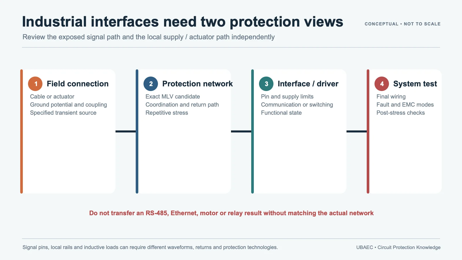
Field wiring can bring electrostatic discharge, repetitive electrical fast transients, switching surge, inductive coupling and ground-potential differences into a PLC, HMI, sensor interface or remote I/O module. A multilayer varistor can be one board-level shunt element when its continuous voltage, clamp behavior, capacitance, leakage, pulse energy, repetition and temperature limits match the actual port.
Start with the Port, Not the PLC Label
Separate the module into power input, digital input, digital output, analog/sensor input and communication ports. Each has a different valid voltage range, source impedance, bandwidth, common-mode range, isolation boundary, wiring length and expected transient. A device that fits a 24 V digital input can be unsuitable for a low-level analog channel or a fast differential line.
KOA identifies NV73 and NV73S varistors in PLC power, digital-control and interface blocks. Sunlord likewise shows an SDV MLV in PLC functional areas. These are useful placement examples, not proof that every series, order code or interface can withstand the project’s pulse network.
Define the Exposure Before Selecting the Clamp
| Question | Evidence to retain | Common error |
|---|---|---|
| What is normal? | Nominal, tolerance, common-mode, polarity, powered-off and fault voltage | Choosing from nominal voltage alone |
| What is the transient? | ESD, EFT/burst or surge generator, coupling path, source impedance, polarity and repetition | Treating all peaks as one waveform |
| What can the signal tolerate? | Leakage, capacitance, bandwidth, threshold and clamp at the protected node | Ignoring loading or residual voltage |
| Where does current return? | Connector, shield/chassis, signal reference, isolation and PCB path | Clamping into a vulnerable logic ground |
| What proves release? | Exact order code, module revision, test level, acceptance and post-stress checks | Using a component rating as equipment compliance |
Use the parameter and test-condition guide to preserve VDC/VAC, varistor-voltage test current, clamping current and waveform, energy duration, capacitance frequency/bias, leakage, tolerance and temperature. Fenghua’s FPV documentation, for example, keeps 8/20 µs current, 10/1000 µs energy and 1 MHz capacitance conditions distinct. Those conditions cannot be converted into a universal PLC-port rating.
Choose a Coordinated Protection Architecture
At a field connector, first decide whether the event should return to chassis/shield, protective earth or circuit reference. Then evaluate series impedance, common-mode choke, filter, isolation, fuse or current limiting, an upstream MOV/GDT/TVS stage and a local MLV. The local device may handle residual energy or protect a nearby IC only when the upstream stage and wiring network bound its stress.
Relay coils, solenoids and motor outputs require a separate inductive-load analysis because load-side switching and repetitive energy are different from a field-interface disturbance. Ethernet-class ports likewise require a dedicated network-interface review that preserves protocol, magnetics, isolation and signal-integrity limits. Those application guides are not linked until their own publication reviews are complete.
Capacitance and Leakage Are Functional Requirements
On a slow discrete input, MLV capacitance may assist filtering. On an analog, sensor or communication channel, the same capacitance can change settling, bandwidth or differential balance. Leakage can shift thresholds or measurement error, especially across temperature. Review the MLV versus TVS comparison as a technology decision, not a ranking.
For an RS-485/RS-422 design, stop at the requirement sheet: data rate, cable, topology, transceiver common-mode and absolute-maximum limits, differential/common-mode capacitance, leakage, fail-safe biasing, isolation, surge/EFT coupling and return path. Do not place or name an MLV until direct interface evidence and measured signal integrity close the hold.
Validate ESD, EFT/Burst and Surge Separately
IEC 61000-4-2:2025 defines equipment ESD methods and expressly does not characterize an ESD protection component by itself. IEC 61000-4-4:2012 addresses repetitive EFT/burst on supply, signal, control and earth ports. IEC 61000-4-5:2014 with its 2017 amendment addresses equipment surge under defined generators, coupling and operating conditions. None turns a datasheet pulse rating into PLC compliance.
- Record the final module, firmware, wiring, grounding, shield and operating mode.
- Run each required ESD, EFT/burst and surge setup with its own level, polarity, coupling and repetition.
- Measure current through the protector and voltage at both the connector and protected IC.
- Monitor function, communication or measurement accuracy during and after exposure.
- Check temperature, leakage, varistor-voltage drift, clamp behavior and physical condition after stress.
- Repeat after alternate components, PCB changes, cable changes or protection-stage changes.
Apply the MLV selection workflow, the layout and mounting guide and the reliability and standards guide. Keep the protector close to the entry point and make the high-current return path short, deliberate and separate from sensitive references.
Minimum Inquiry Data
- port function, normal/common-mode/fault voltage and isolation scheme;
- signal bandwidth or data rate, leakage and capacitance budget;
- ESD, EFT/burst and surge generators, levels, coupling, source impedance and repetition;
- cable, shield, grounding, series components and upstream protection;
- temperature, package, exact qualification scope and module acceptance criteria.
Summary
MLV protection for PLC and industrial I/O is a port-and-system decision. Generic placement is supported; RS-485/RS-422 recommendation remains held. Release an exact device only after its electrical conditions, coordination, layout and final-module behavior are documented.
Use the MLV Technical Resources & Datasheet Library, return to the MLV Knowledge Map, or ask UBAEC with the port and test plan.
Continue Reading
- Industrial Ethernet and Network-Interface MLV Protection
- Motor, Solenoid and Relay Transient Protection with MLVs
- MLV PCB Layout, Mounting and Soldering Reliability
- How to Select an MLV: A Practical Engineering Workflow
Official Technical References
The following first-party, standards-organization or publisher records support the technical boundaries used in this article. Always verify the current revision and the exact product scope before design release.
- PLC Application Guide
- PLC Application Guide
- Multilayer Chip Varistors
- IEC 61000-4-2:2025 – Electromagnetic compatibility (EMC) – Part 4-2: Testing and measurement techniques – Electrostatic discharge immunity test
- IEC 61000-4-5:2014+AMD1:2017 CSV – Electromagnetic compatibility (EMC) – Part 4-5: Testing and measurement techniques – Surge immunity test
- IEC 61000-4-4:2012 – Electromagnetic compatibility (EMC) – Part 4-4: Testing and measurement techniques – Electrical fast transient/burst immunity test











