

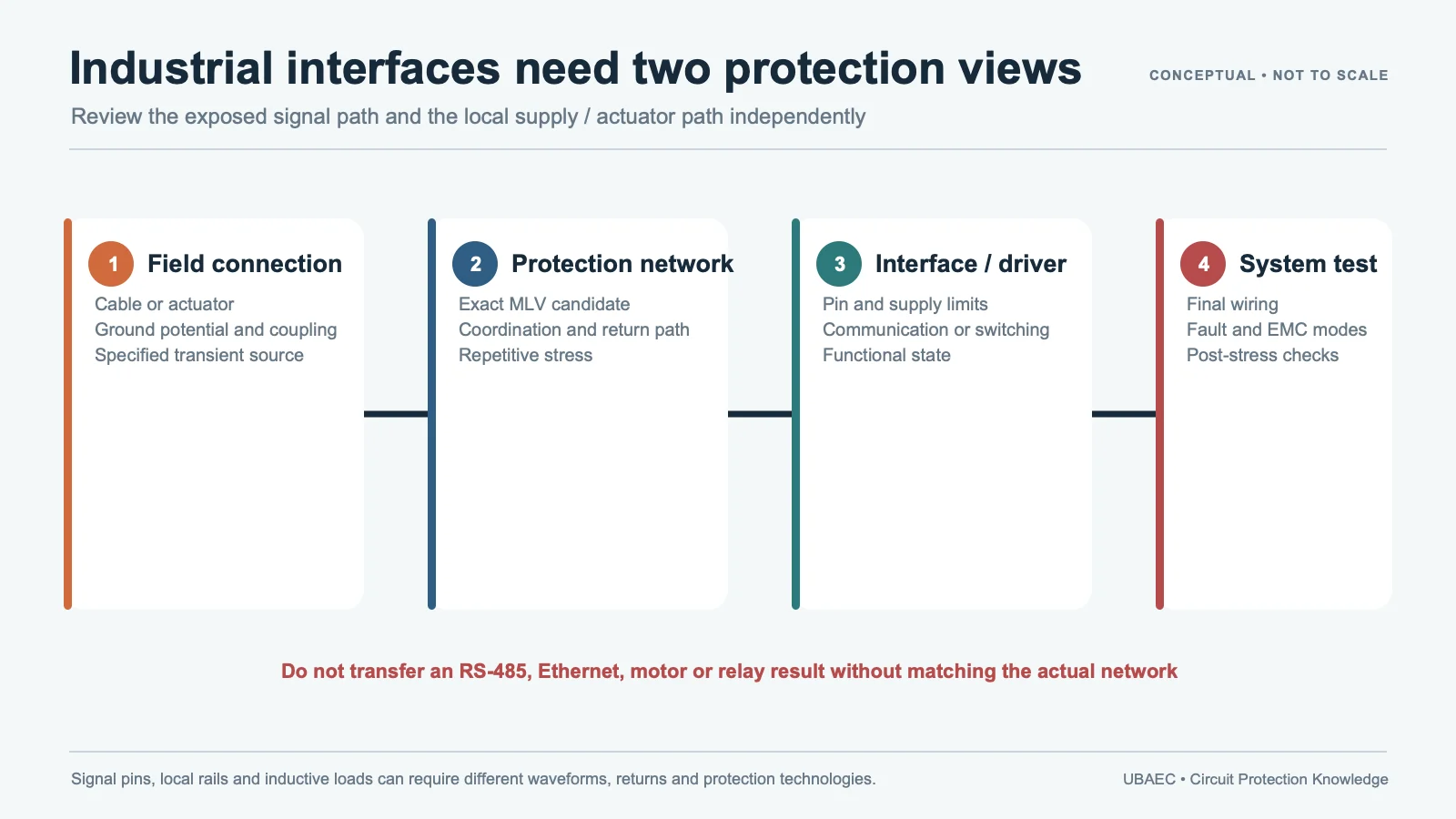
Industrial Ethernet is not one electrical interface. Conventional multi-pair Ethernet, Single-Pair Ethernet, isolated and non-isolated ports, copper runs inside a cabinet and cables leaving the equipment can face different signal-integrity, common-mode, ESD and surge requirements. A low-capacitance MLV is one candidate only when the exact protocol, topology and installation are known.
Do not use a PLC diagram or automotive Ethernet datasheet as universal industrial Ethernet proof. Those sources can show placement or relevant component behavior, but the final recommendation must match the industrial protocol, magnetics/isolation, cable, power-over-data arrangement, test network and acceptance criteria.
Define the Interface Architecture
| Layer | Required inputs | Protection question |
|---|---|---|
| Connector/cable | Cable type/length, shield, environment, accessible contacts and installation boundary | Where does ESD or surge enter and return? |
| Signal path | Protocol/data rate, differential impedance, common-mode range, topology and PoDL/PoE state | What loading and residual voltage are acceptable? |
| Magnetics/isolation | Transformer/CMC, isolation rating, center taps, chassis strategy and creepage/clearance | Is the protector on the cable or PHY side, and can it compromise isolation? |
| Equipment test | ESD/surge generator, coupling, source impedance, polarity, repetition and functional criterion | What final-port result proves release? |
Use the parameter and test-condition guide. Capacitance needs frequency, amplitude, DC bias, tolerance and typical/maximum basis. S-parameters need the exact device, topology, fixture and frequency range. ESD dynamic behavior and surge Vc are separate measurements.
What the Current Evidence Supports
KYOCERA AVX’s current Single-Pair Ethernet page discusses low-capacitance AP-series varistors for industrial and automotive Ethernet, including PLCs, robotics, sensors, safety relays, switches and light curtains. The page combines connector/solution context with component discovery, while its linked ASPGuard datasheet maps exact parts to automotive 100BASE-T1 and 1000BASE-T1 evidence. The industrial application list is useful discovery, but the automotive OPEN Alliance mapping cannot be transferred to every industrial SPE or Ethernet implementation.
TDK’s mode-conversion application note shows why imbalance between two ESD protectors can worsen differential-to-common-mode conversion and EMI. Sunlord’s PLC guide shows an MLV in an Ethernet-expansion context but provides placement evidence only. Together these sources justify a matched-condition evaluation, not a protocol-specific part recommendation.
Use the Automotive Ethernet/RF guide only for evidence-boundary comparison and the high-speed port method for technology-selection questions. Industrial release remains its own test plan.
Coordinate the Protection Stack
At the connector, define shield/chassis bonding and the shortest intended transient-current path. Then evaluate common-mode choke or magnetics, TVS/ESD array, possible low-capacitance MLV, GDT or upstream surge stage, series impedance and PHY protection. Component order and return path can change both clamp performance and EMC.
For an isolated port, check whether any shunt element bridges or loads the isolation boundary. For a powered SPE/PoDL path, include continuous voltage, power injection and fault current. For cables leaving the building or cabinet, installation-level surge energy may require a coordinated upstream stage rather than a small board-level MLV.
Use the MLV versus TVS comparison, the layout guide and the PLC/industrial-I/O evidence boundary. The RS-485/RS-422 hold on the latter remains unrelated and must not be “closed” by Ethernet evidence.
Validate Signal, Isolation and Immunity Separately
Keep cable-side common mode, pair-to-pair or differential injection and power-port injection distinct. The surge generator and coupling network can change when the cable is shielded, unshielded, indoor, outdoor or powered. Record the protector’s actual current rather than assuming the open-circuit generator voltage appears across it.
Power over Data Line or Power over Ethernet adds a continuous and fault-current path that a data-only evaluation misses. Check start-up, disconnect, polarity, power-sourcing/receiving behavior and coordination with fusing or current limiting. A part that preserves the eye may still be thermally or electrically unsuitable for the powered state.
- Verify exact protector lifecycle, package, capacitance tolerance and working voltage.
- Measure insertion/return loss, mode conversion, impedance and link performance with the final layout.
- Test isolation, leakage and powered/unpowered/fault states where applicable.
- Run IEC 61000-4-2 ESD and IEC 61000-4-5 surge with documented coupling and cable setup.
- Measure protector current and voltage at connector, magnetics/isolation and PHY nodes.
- Check link/function during exposure and leakage, drift, thermal and physical condition after stress.
IEC 61000-4-2:2025 Edition 3.0 is an equipment ESD method and explicitly is not intended to characterize protection circuits by itself. IEC 61000-4-5:2014 with the 2017 amendment defines equipment surge methods and does not prove an MLV rating or direct-lightning capability. Use the reliability and standards guide and the selection workflow.
Change and Alternate Gate
Reopen the decision after any protocol, data-rate, cable, connector, shield, magnetics, isolation, PoDL/PoE, PCB or order-code change. An alternate must repeat the capacitance/S-parameter, clamp, isolation, thermal and system tests; nominal capacitance or package equivalence is insufficient.
Minimum Inquiry Data
- Ethernet/SPE variant, data rate, topology, cable, connector and shield;
- magnetics/isolation/CMC, PoDL/PoE state and PHY limits;
- capacitance tolerance, S-parameter/mode-conversion and link budget;
- ESD/surge networks, coupling, source impedance, repetition and acceptance;
- temperature, package, lifecycle, exact order code and PCB current-return path.
Summary
Industrial Ethernet protection is released by the exact interface architecture and measured final port. MLVs remain one conditional technology candidate; application lists and automotive mappings do not replace protocol-specific validation.
Use the MLV Technical Resources & Datasheet Library or return to the MLV Knowledge Map.
Continue Reading
- PLC and Industrial I/O Protection with MLVs — RS-485 Evidence Boundary
- MLV vs Resin and Polymer ESD Suppressors
- MLV PCB Layout, Mounting and Soldering Reliability
- How to Select an MLV: A Practical Engineering Workflow
Official Technical References
The following first-party, standards-organization or publisher records support the technical boundaries used in this article. Always verify the current revision and the exact product scope before design release.
- PLC Application Guide
- ASPGuard low-capacitance varistors datasheet
- Deterioration of Mode Conversion and EMI Due to Incorrect Selection of ESD Protective Components
- IEC 61000-4-2:2025 – Electromagnetic compatibility (EMC) – Part 4-2: Testing and measurement techniques – Electrostatic discharge immunity test
- IEC 61000-4-5:2014+AMD1:2017 CSV – Electromagnetic compatibility (EMC) – Part 4-5: Testing and measurement techniques – Surge immunity test











