

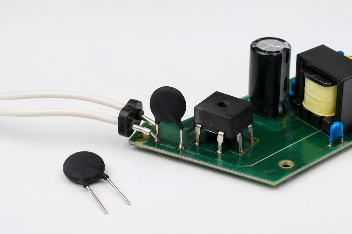
Does the 5 Ω, 10 Ω, or 20 Ω printed in an NTC inrush-current limiter’s datasheet predict the voltage it will drop while a power supply is running? Usually not. That value is normally the rated resistance at 25 °C, R25, measured at low power. It is important during a cold start, but operating current self-heats the negative temperature coefficient (NTC) ceramic and drives its resistance downward. Steady-state voltage drop therefore depends on load current, ambient temperature, airflow, mounting, and the time allowed to reach thermal equilibrium.
Cold start and steady state are different operating points
An NTC inrush-current limiter is normally placed in series with the input path. At first energization, the bulk capacitor is discharged and the NTC is close to ambient temperature. Its relatively high cold resistance combines with source and wiring impedance to reduce the charging-current peak. A first estimate can start with peak input voltage, the maximum acceptable inrush current, and capacitor energy, but it must be checked against the manufacturer’s capacitance or pulse conditions and then validated in the actual circuit.
After startup, continuous current produces I²R heating in the thermistor. Because the material has a negative temperature coefficient, the rising body temperature reduces resistance. A new equilibrium is reached when electrical heating is balanced by heat loss to the surrounding air, leads, and board. A device rated 10 Ω at 25 °C can consequently operate at a fraction of an ohm near its rated current. Using 10 Ω to calculate the continuous voltage drop greatly overstates normal loss; using the minimum hot resistance to predict the first cold start seriously understates inrush current.
Why hot resistance is not one fixed number
The familiar relationships Vdrop = I × Rhot and P = I² × Rhot still apply as steady-state approximations. The difficulty is that Rhot is an operating result rather than a universal constant. Higher continuous current creates more self-heating and generally lowers the equilibrium resistance. At light load or standby current, the same part may not become hot enough to reach the low resistance shown near its maximum current. Light-load, typical-load, and full-load losses should not be calculated with one assumed hot value.
Cooling conditions shift that equilibrium. Forced air, a nearby metal structure, or heat conducted through leads and copper can keep the body cooler and its resistance higher at the same current. A sealed enclosure, adjacent heat source, or high ambient temperature changes both temperature and reliability margins. Manufacturer voltage-current curves and thermal values are often characterized in still air at 25 °C. They are useful engineering inputs, but they are not proof that an installed component will reach the same resistance inside a particular enclosure.
Read R25, Imax, Ctest, and Rmin as separate limits
R25 is the low-power resistance at the rated temperature. It mainly describes the initial damping available from a cold device. Imax is the maximum permissible continuous current under defined operating conditions; an AC rating is normally an RMS value. Ctest is a tested capacitance at a stated AC voltage and test method. It ties capacitor size to charging voltage, pulse energy, and cycling conditions, so a capacitance number cannot be transferred between 110/120 V AC and 230/240 V AC without checking the relevant row.
Some datasheets also specify Rmin, or minimum resistance at maximum current. TDK’s S235 table separately lists R25, Imax from 0 to 65 °C, Ctest at 230 V AC and 110 V AC, and Rmin at Imax in a 25 °C ambient. For the 10 Ω member of that particular series, the table gives Imax = 3 A and Rmin = 0.206 Ω. This is a product-specific example under stated conditions. It does not mean every 10 Ω inrush limiter will have that hot resistance, or that an S235 installed in any enclosure will operate at exactly 0.206 Ω.
A TDK application note also describes an estimate of continuous-current resistance using RNTC = k × In, with k and n taken from the individual part data. The note limits that approximation to 0.3 × Imax < I ≤ Imax and to operation in still air at an ambient temperature of 25 °C. Extrapolating it into standby current, forced-air cooling, potting, or an undefined ambient removes the conditions that make the estimate useful.
Selection must satisfy startup and running constraints
- Define maximum line voltage, turn-on phase, source impedance, rectifier topology, bulk capacitance, and the largest permissible current peak.
- Select enough cold resistance to provide initial damping, including R25 tolerance and the possible initial temperature of the NTC.
- Check Ctest or the manufacturer’s pulse-energy method at the applicable input voltage and cycling conditions.
- Check Imax at the highest continuous RMS or DC current and apply the stated ambient-temperature derating.
- Estimate or measure hot resistance, voltage drop, dissipation, and body temperature at standby, light, typical, and maximum load.
- Validate a short interruption and hot restart, not only the first start from room temperature.
The test record should preserve line voltage and phase, source impedance, bulk capacitance, ambient temperature, airflow, previous on-time, off-time, load current, and measurement location. Allow the temperature to become reasonably stable before reporting steady-state voltage drop, and record component temperature at the same time. A note saying that a “10 Ω NTC had acceptable loss” cannot be reproduced without those conditions.
Hot restart is a separate failure case
After power is removed, an NTC requires time to cool toward ambient and recover its high resistance. A thermal cooling time constant describes a specified fractional reduction in temperature difference, not complete recovery. The TDK S235 datasheet, for example, lists an approximate cooling time constant of 60 s in still air. That does not establish a universal 60-second safe restart time, and one time constant does not mean that the device has completely returned to R25.
If the equipment is energized again after only a few seconds, the bulk capacitor may have discharged substantially while the NTC remains hot and low in resistance. The second inrush peak can then be higher than the first cold-start peak. Equipment with a defined hot-restart requirement should specify the shortest interruption, residual bus voltage, initial thermistor temperature, and worst line phase. An active limiter, a precharge resistor with a relay, or another controlled soft-start arrangement may be more appropriate when repeatable restart behavior is required.
Do not confuse an inrush limiter with protection coordination
An NTC can reduce charging current, nuisance fuse operation, and stress on rectifiers or switch contacts, but it is not a complete overcurrent protection system. Imax does not replace a fuse time-current curve or interrupting rating, and Ctest does not certify the finished power supply. The design must still consider the fuse, rectifier, relay or bypass path, abnormal current, creepage and clearance, component surface temperature, and the equipment safety standard.
Parallel connection is also not a simple route to more current capacity. TDK warns that inrush-current limiters should not be connected in parallel because the lower-resistance part can take most of the current and overheat. If a high-power design exceeds the range of a single device, use a manufacturer-supported topology and validate current sharing rather than assuming two nominally equal NTCs will divide current evenly.
Common questions
Does a higher cold resistance always mean higher running loss?
No. Parts with different diameter, material system, Imax, and resistance-current curves can have very different hot resistance. Compare Rhot or the voltage-current data at the same load and ambient condition, not R25 alone.
Can hot resistance be measured with a handheld ohmmeter?
Removing power starts the cooling process immediately, and an ohmmeter does not reproduce operating current. A better method is to measure current and the in-circuit voltage drop at thermal equilibrium, then calculate an equivalent hot resistance. Any measurement on mains circuitry requires appropriate isolation, probes, clearances, and qualified personnel.
Is operation below Imax enough to approve the design?
No. Imax is one component limit. Ctest, R25 tolerance, ambient derating, startup count, body temperature, mounting space, hot restart, abnormal operation, and equipment-level safety requirements remain separate checks.
Should steady-state loss be calculated at full load only?
No. Full load may produce the lowest hot resistance, while a long light-load condition can leave the device cooler and more resistive. Evaluate both voltage-drop performance and temperature at all persistent operating modes.
Practical conclusion
R25 is an essential input for cold-start damping, but it is not the resistance that determines normal running voltage drop. Estimate or measure Rhot at the actual current, ambient, and cooling condition, then use Imax and Ctest to protect the continuous-current and startup-energy boundaries. A complete validation covers cold start, steady operation at several loads, high ambient temperature, and hot restart. Treating one cold-resistance value as the NTC’s behavior throughout the power cycle misjudges both the inrush peak and the operating loss.
Continue with Electronic Component Types and Functions, AC-DC Power-Supply Protection, Protection Circuit Basics, and the UBAEC contact page.












