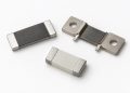
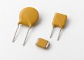
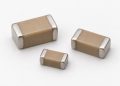
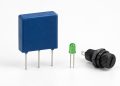
Class X and Class Y capacitors both suppress interference on AC mains circuits, but their classification is not determined by package shape, color, or dielectric. It begins with connection position and the hazard created by a failure. Class X is normally used line-to-line or line-to-neutral. Class Y is used from line to protective earth, accessible ground, or across certain isolation boundaries, where a short-circuit failure could create an electric-shock path.
That is why equal capacitance and equal voltage markings do not establish interchangeability. A substitution review must cover connection position, X or Y subclass, rated AC voltage, impulse category, current certification evidence for the exact series, creepage and clearance in the assembly, environmental limits, and the equipment’s allowable leakage current.
Class X and Class Y address different hazards
An X capacitor shunts differential-mode high-frequency noise between supply conductors. If it fails short, the main concerns are overcurrent, heating, and fire, so the system also relies on fusing, flame-retardant construction, and source protection. A Y capacitor shunts common-mode noise between the mains side and earth or another reference. A short there could expose an accessible side to hazardous voltage, so insulation, impulse, and fail-safe requirements are more stringent.
X and Y are therefore not simple quality ranks. A part approved only as X2 cannot be moved into a Y position merely because its continuous voltage rating appears sufficient. A dual-marked X1/Y2 series must still be applied according to the rating that corresponds to the actual connection.
Subclass numbers are not a complete selection rule
IEC 60384-14 divides X and Y capacitors into subclasses associated with application conditions, impulse tests, and insulation requirements. Use the current equipment standard, component datasheet, and valid agency certificate rather than a remembered table detached from its standard edition. KEMET’s guidance gives a useful directional example: Y2 may not replace Y1, while a Y1 part may replace Y2 when the voltage and all other requirements are equal or higher.
That example is not permission to replace every Y2 with any Y1. Capacitance, dimensions, impulse rating, approved voltage, temperature, frequency, leakage-current budget, construction, and the certificate’s covered ordering code must still match the design.
Rated voltage is only one gate
The AC rating describes continuous operation, while the safety subclass also captures impulse and insulation behavior. Using an impulse withstand value as a higher continuous operating voltage, or comparing only capacitance and VAC, removes the safety basis. Equipment overvoltage category, pollution degree, altitude, and product-specific insulation requirements may add further constraints.
For a Y capacitor, increasing capacitance normally increases line-frequency leakage current. The ideal capacitive current can be estimated as I≈2πfCV, but the actual equipment calculation must use maximum voltage and frequency, capacitance tolerance, all Y capacitors together, the full filter network, and the prescribed leakage or touch-current test method. Passing an EMI scan does not prove electric-shock safety.
A five-step selection and substitution method
1. Mark the connection on the schematic
Identify whether the capacitor is line-to-line, line-to-neutral, line-to-protective-earth, line-to-accessible reference, or across an isolation barrier. Do not infer the class from an abbreviated old BOM description such as a capacitance code and VAC value.
2. Establish the required subclass
Derive the minimum X or Y subclass from the applicable equipment standard, surge environment, and insulation architecture. Then verify the exact manufacturer’s series and ordering code in its datasheet and agency certificate. A body marking is a traceability clue, not a substitute for the certificate scope.
3. Check continuous, impulse, and environmental ratings
Compare rated AC or DC voltage, stated impulse tests, temperature range, damp-heat category, and expected service environment. High humidity can contribute to capacitance loss in some metallized-film constructions, so use the series-specific environmental qualification rather than a generic material assumption.
4. Recalculate electrical performance
Check capacitance, tolerance, dissipation, frequency behavior, and the total leakage or touch-current contribution of Y capacitors. Different dielectric systems, lead structures, and layouts can have different high-frequency impedance even at the same nominal capacitance. Repeat conducted-emissions, radiated-emissions, and immunity tests after substitution.
5. Preserve approval and equipment evidence
Record manufacturer, series, ordering code, approval marks, certificate number, and applicable conditions, then complete the equipment-level safety and EMC verification. RoHS documentation is not a safety-capacitor approval. The component abbreviations and documentation guide helps distinguish material, qualification, and certification terms.
Common mistakes
A conventional film or ceramic capacitor does not become suitable for an X or Y position merely because its voltage rating is higher. Similar blue disc packages can contain a safety capacitor, a varistor, or a conventional ceramic capacitor; identify the complete part number and supporting documents. If the input also uses an MOV, verify surge clamping, fusing, and safety filtering as separate functions. The guide to MOV fuses and thermal disconnects shows why different hazards require different evidence.
For system context, use the electronic-component function map. When comparing continuous and temporary voltage withstand, the conditional reading method in the TOV versus MCOV guide is a useful analogy, although safety capacitors follow their own standards and tests.
FAQ
Can X2 replace Y2?
Not on the basis of voltage rating. A Y location has different shock-hazard, insulation, and certification requirements and needs a part approved for the required Y subclass.
Can Y1 always replace Y2?
Only if operating voltage, capacitance, size, environmental rating, certificate scope, and the equipment leakage-current budget all remain acceptable. The subclass name alone is insufficient.
Will equal capacitance give equal filtering?
Not necessarily. Dielectric, construction, leads, and layout change high-frequency impedance and parasitics. Repeat EMC verification.
Does RoHS compliance prove an X or Y approval?
No. RoHS addresses restricted substances; X and Y approvals address safety-standard tests and recognized component scope.
Conclusion
The first distinction between X and Y capacitors is connection position and failure hazard, not appearance. Start from the schematic, then verify subclass, continuous and impulse ratings, current approval evidence, environment, leakage current, and EMC behavior. If any of those conditions is missing, capacitance and voltage alone cannot support an equivalence claim.
References: KEMET, R53 X2 Capacitors technical resource; KEMET Ceramics FAQ and Application Guide; KEMET C700 X1/Y1 datasheet.