
UBAEC | Electronic Components & Application Insights
  • Components
  • Applications
  • Wiki
    • Submit a Technical Question
  • Technical Topics
  • Industry News
No Result
View All Result
  • MOV
  • MLV Knowledge Map
UBAEC | Electronic Components & Application Insights
  • Components
  • Applications
  • Wiki
    • Submit a Technical Question
  • Technical Topics
  • Industry News
No Result
View All Result
UBAEC | Electronic Components & Application Insights

MOV Placement: Line-to-Line vs Line-to-Ground Protection

Viki by Viki
2026-08-09
in Protection Circuits
A A
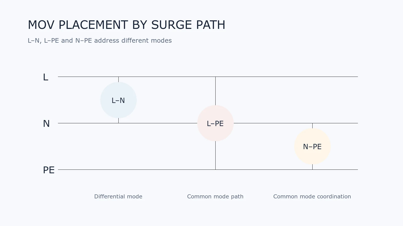
Diagram comparing MOV placement from line to neutral, line to protective earth and neutral to protective earth
Share on FacebookShare on Twitter

An MOV placed across line and neutral does not solve the same problem as an MOV placed from line to protective earth. The terminals, surge mode, earthing system and safety requirements determine which current path the protection creates.

This guide uses the common abbreviations L (Line), N (Neutral) and PE (Protective Earth). Final design must follow the equipment standard, installation category and regional wiring system.
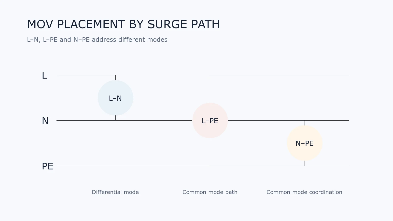
Diagram comparing MOV placement from line to neutral, line to protective earth and neutral to protective earth
L–N, L–PE and N–PE branches create different surge-current paths and cannot be treated as interchangeable.

Differential-Mode and Common-Mode Surges

A differential-mode surge appears between current-carrying conductors, such as L and N. A common-mode surge appears between one or more current-carrying conductors and earth.

A surge generator and coupling network may apply different test modes. The circuit should be reviewed against the actual test setup rather than the generic phrase “surge protected.”

MOV From Line to Neutral (L–N)

An L–N MOV provides a shunt path for differential-mode transients. It is common near an AC input, after the appropriate upstream overcurrent protection, with a short low-inductance connection.

Key checks include:

  • maximum continuous AC voltage including mains tolerance;
  • temporary-overvoltage exposure;
  • clamping level at the specified surge current;
  • fuse and thermal-disconnect coordination;
  • distance from heat-sensitive or flammable material.

MOV From Line to Protective Earth (L–PE)

An L–PE branch can divert common-mode surge current toward protective earth. That function also introduces safety considerations because the component bridges a hazardous conductor and accessible-earth network.

The device construction, approvals, creepage, clearance, fault behavior, leakage and equipment class must be reviewed. Do not add an L–PE MOV merely because an L–N test passed poorly.

MOV From Neutral to Protective Earth (N–PE)

An N–PE branch may be used as part of a coordinated common-mode protection network, but neutral is not universally at earth potential. Wiring faults, installation topology and regional systems can produce significant N–PE voltage.

Selection must consider the worst continuous and temporary voltage across this branch, not only the ideal normal condition.

Why Three MOVs Are Not Automatically a Complete Solution

A network using L–N, L–PE and N–PE MOVs changes surge-current distribution. The branch that conducts first can affect the current and residual voltage seen by the others. Lead and trace inductance can add to the measured peak voltage.

Coordination requires system-level testing. It also requires a defined response if one branch is disconnected by thermal protection.
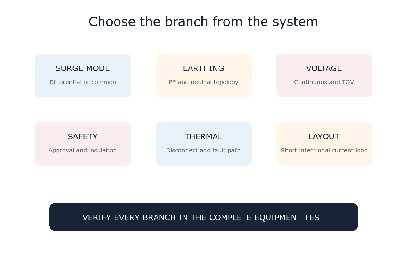
Checklist for selecting MOV positions based on surge mode, earthing system, continuous voltage, safety approval, thermal protection and layout
Choose the branch from the required surge path and safety analysis, then verify the complete assembly.

Equipment With No Protective Earth

Class II or unearthed equipment does not provide a PE node for an ordinary L–PE MOV branch. Protection topology must respect the insulation system and applicable standard. Do not create a pseudo-earth connection that compromises reinforced or double insulation.

Leakage and Insulation Testing

Although a correctly selected MOV is high resistance during normal operation, it still has leakage current and capacitance. Earth-connected protection can influence leakage-current measurements, dielectric testing and insulation coordination.

Use device limits across temperature and end of life, not only a typical room-temperature value.

Where Should the Network Be Placed?

The surge branch should usually be close to the entry point and the intended current return path. Keep the loop short and avoid routing surge current through sensitive signal or control ground. The exact position relative to filters, switches and fuses depends on the required safety and EMC behavior.

Design Review Checklist

  • Identify every required test mode and generator connection.
  • Document the earthing and equipment insulation class.
  • Calculate maximum continuous and temporary voltage for each branch.
  • Check component approval and abnormal-operation requirements.
  • Coordinate overcurrent and thermal disconnection.
  • Model or measure residual voltage at the protected load.
  • Review leakage, capacitance, creepage and clearance.
  • Test the assembled product under the applicable standard.

Related Guides

  • MOV Protection Circuit Basics
  • MOV Failure Modes and Thermal Protection
  • MOV Surge Waveforms
  • How to Select an MOV

Reference

  • TDK Electronics — SIOV Metal-Oxide Varistors, Application Notes

For a private topology review, use Ask UBAEC and include the input diagram, earthing arrangement, equipment class, mains range and surge-test modes.

Tags: Common Mode SurgeLine-to-GroundLine-to-LineMOV
Next Post
IEC 61000-4-5 combination-wave surge test chain from generator through coupling network to equipment under test

IEC 61000-4-5 Surge Test Explained: Waveforms, Coupling and Interpretation

MOV Standards and Approvals: IEC 61051, IEC 61643 and UL 1449

  • Trending
  • Comments
  • Latest
Blue radial metal-oxide varistors used for transient overvoltage protection

What Is a Varistor? MOV Basics and Key Parameters

2026-09-07
Populated electronic circuit board on a laboratory test bench

What Are Electronic Components? Common Types, Functions and Selection Basics

2026-09-07
Conceptual MLV operating regions from normal leakage through transient conduction to post-pulse recovery

How Multilayer Varistors Work

2026-09-07
IEC 61000-4-5 combination-wave surge test chain from generator through coupling network to equipment under test

IEC 61000-4-5 Surge Test Explained: Waveforms, Coupling and Interpretation

2026-08-10
Populated electronic circuit board on a laboratory test bench

What Are Electronic Components? Common Types, Functions and Selection Basics

1
Oscilloscope probes measuring surge residual voltage between the protected node and local return after an MOV

Why Do MOV Leads and PCB Traces Increase Residual Voltage?

1
Blue radial metal-oxide varistors used for transient overvoltage protection

What Is a Varistor? MOV Basics and Key Parameters

0
Multilayer chip varistors and molded surface-mount MOV packages used for circuit protection

What Is an SMD MOV? Types, Parameters and Applications

0
GDT devices with a surge generator and oscilloscope in a circuit-protection test setup

Why Can a GDT Keep Conducting After a Surge?

2026-09-16
Single two-terminal MLCC in a measurement fixture with a completed thermal-history backdrop and a conceptual slow downward time trend

MLCC Aging and De-Aging: Capacitance After Reflow and Referee Time

2026-09-15
Disc MOV on a test fixture with a thermal image and a time-voltage withstand curve

How to Read MOV TOV Data: Temporary Withstand Is Not MCOV

2026-09-14
Three-lead thermally protected MOV connected to a status LED and optocoupler test board

How Should the Third Lead of a Thermally Protected MOV Be Wired?

2026-09-13

Need help selecting a component?

Share the operating voltage, package, surge or ESD conditions. We will help you identify the parameters that matter.

Submit a technical question

About UBAEC

UBAEC provides electronic component information, circuit protection knowledge, application guidance, and inquiry support for engineers and sourcing teams.

Categories

  • Application Notes
  • Automotive
  • Basics
  • Consumer Electronics
  • Cross Reference
  • Downloads
  • Industrial Control
  • Industry Insights
  • LED Lighting
  • Manufacturers
  • MLV
  • Parameters
  • Protection Circuits
  • Selection Guide
  • Standards
  • Technical Q&A
  • Telecommunications

Recent Post

  • Why Can a GDT Keep Conducting After a Surge?
  • MLCC Aging and De-Aging: Capacitance After Reflow and Referee Time
  • About
  • Contact
  • Privacy Policy
  • 中文

© 2026 UBAEC — Electronic Components & Application Insights. All rights reserved.

No Result
View All Result
  • Home
  • Component Center
  • Applications
  • Technical Wiki
  • News
  • Contact

© 2026 UBAEC — Electronic Components & Application Insights. All rights reserved.









