
UBAEC | Electronic Components & Application Insights
  • Components
  • Applications
  • Wiki
    • Submit a Technical Question
  • Technical Topics
  • Industry News
No Result
View All Result
  • MOV
  • MLV Knowledge Map
UBAEC | Electronic Components & Application Insights
  • Components
  • Applications
  • Wiki
    • Submit a Technical Question
  • Technical Topics
  • Industry News
No Result
View All Result
UBAEC | Electronic Components & Application Insights

Can MOVs Be Connected in Series or Parallel?

Viki by Viki
2026-08-09
in Technical Q&A
A A
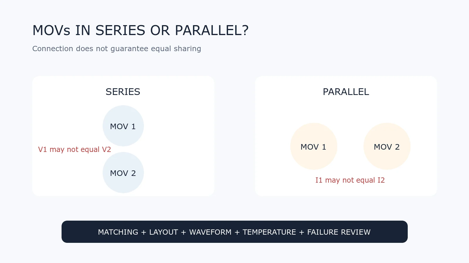
Comparison diagram of two MOVs connected in series and in parallel with warnings about unequal voltage and current sharing
Share on FacebookShare on Twitter

MOVs can be drawn in series or parallel on a schematic, but the connection does not automatically multiply the rating. Device tolerance and the steep nonlinear current-voltage curve can cause unequal voltage or current sharing.

The short answer is: series or parallel use requires manufacturer guidance and validation of the complete assembly.
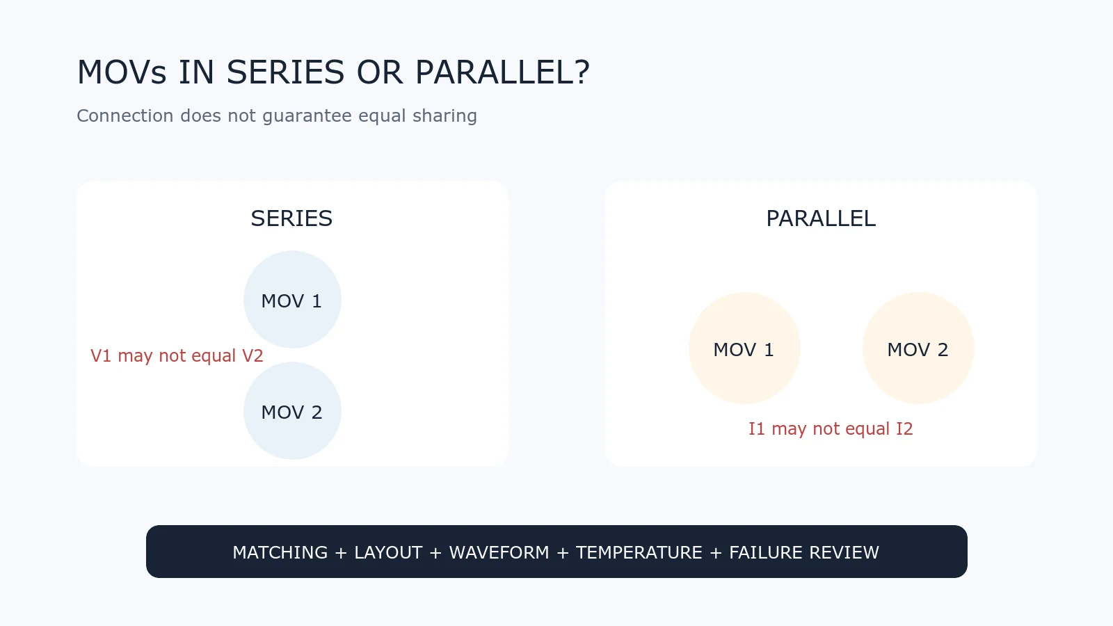
Comparison diagram of two MOVs connected in series and in parallel with warnings about unequal voltage and current sharing
Series and parallel circuits have different sharing problems. Neither should be rated by simple arithmetic alone.

Why MOV Tolerance Matters

An MOV’s varistor voltage is specified with tolerance at a reference current. Two parts carrying the same ordering code are similar, not electrically identical. Small differences become important because MOV current rises steeply with voltage.

What Happens With MOVs in Parallel?

Parallel MOVs see approximately the same terminal voltage, but they may not carry equal surge current. The device with the lower effective varistor voltage can conduct earlier and take more of the pulse. Its additional heating can further change the current distribution.

Therefore, two MOVs in parallel do not automatically provide twice the surge-current or energy rating. Lead length, PCB trace impedance, thermal coupling and production spread also influence sharing.

Questions to verify for a parallel design

  • Does the manufacturer explicitly allow or characterize parallel operation?
  • Are the devices from a controlled matching group or the same production lot?
  • Are the current paths geometrically symmetrical and low in inductance?
  • Has dynamic current sharing been measured under the required waveform?
  • What happens if one MOV ages or fails before the other?

What Happens With MOVs in Series?

Series MOVs divide the applied voltage, but the division may not be equal. Leakage-current and capacitance differences affect steady-state and transient voltage distribution. During a fast event, parasitic capacitance and layout become more significant; during continuous voltage, leakage characteristics and temperature matter.

Two series MOVs should not be assumed to support exactly twice the continuous voltage or twice the clamping voltage. The total residual voltage also changes, which may no longer protect the downstream circuit adequately.

Questions to verify for a series design

  • How is steady-state voltage shared at minimum and maximum temperature?
  • How is transient voltage shared during the specified surge waveform?
  • Are balancing components required and are they approved for the application?
  • Does the resulting clamping level remain below the protected circuit’s withstand voltage?
  • What clearance, creepage and insulation requirements apply?
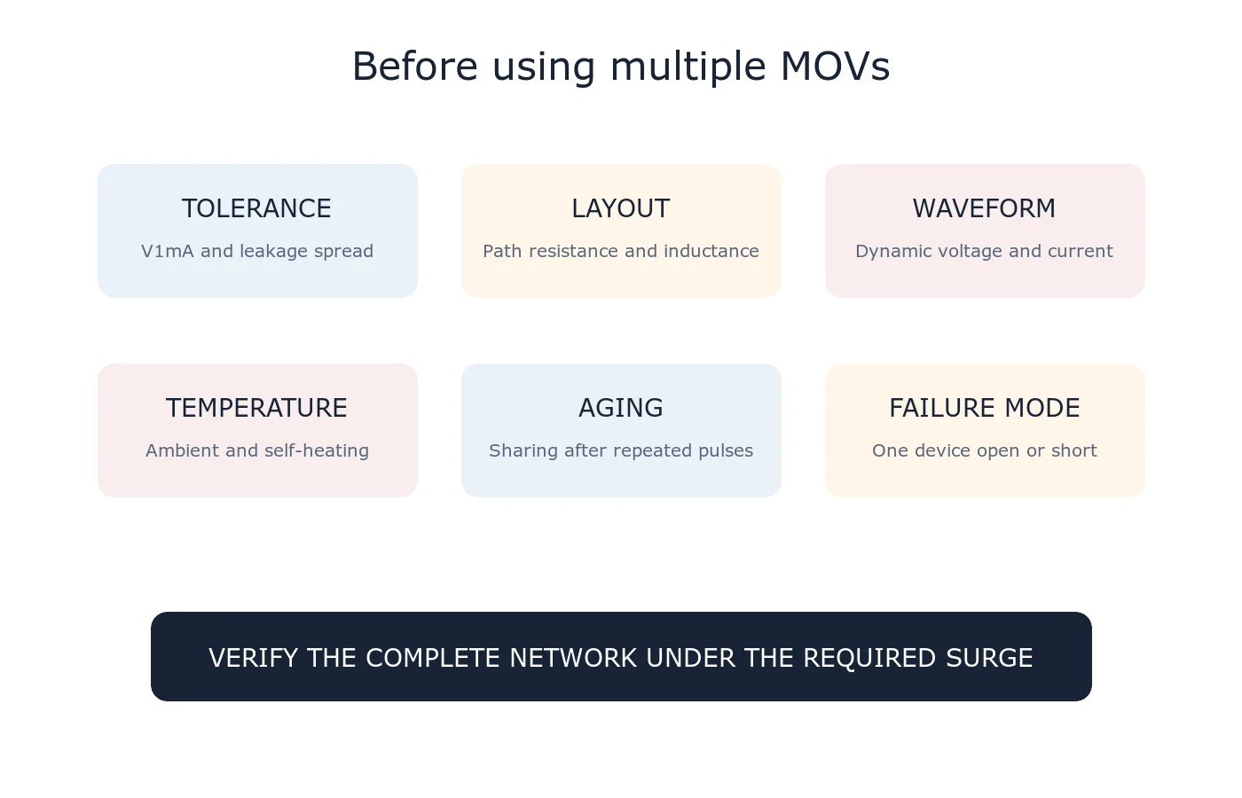
Engineering checklist for MOV series and parallel connections covering tolerance, layout, temperature, waveform, aging and failure mode
Sharing must be checked dynamically under the real pulse and thermally under the real operating environment.

Can Balancing Resistors Solve Series Sharing?

Balancing resistors may improve static voltage distribution in some high-voltage networks, but they add continuous power loss and do not by themselves guarantee equal sharing during a fast surge. Their voltage rating, tolerance, fault behavior and safety spacing must also be designed.

Does Symmetrical Layout Solve Parallel Sharing?

Symmetrical layout is important, but it cannot remove the MOVs’ electrical tolerance. It reduces avoidable path imbalance. The final assembly still needs surge testing and temperature review.

When Is One Larger MOV Better?

If a single qualified device can meet voltage, clamping, surge, energy, temperature and safety requirements, it is usually easier to characterize than an unvalidated multi-MOV network. Physical size, availability and system redundancy may still lead to other choices.

What About Coordinated Protection Stages?

Using different protection devices at different circuit locations is not the same as placing identical MOVs directly in parallel. A coordinated design may use an upstream MOV for higher-energy diversion and a downstream TVS diode or other device for tighter protection, with deliberate impedance between stages.

See MOV vs TVS Diode and MOV Protection Circuit Basics.

Practical Rule

Do not calculate a multi-MOV rating by adding catalog numbers alone. Obtain manufacturer guidance, retain waveform and temperature conditions, analyze single-device failure and test the complete network.

For a private review, use Ask UBAEC and include the circuit diagram, normal voltage, maximum voltage, surge waveform, expected pulse count and the complete MOV part numbers.

Reference

  • TDK Electronics — SIOV Metal-Oxide Varistors, Application Notes
Tags: Current SharingMOVParallel ConnectionSeries ConnectionVoltage Sharing
Next Post
Diagram comparing MOV placement from line to neutral, line to protective earth and neutral to protective earth

MOV Placement: Line-to-Line vs Line-to-Ground Protection

IEC 61000-4-5 combination-wave surge test chain from generator through coupling network to equipment under test

IEC 61000-4-5 Surge Test Explained: Waveforms, Coupling and Interpretation

  • Trending
  • Comments
  • Latest
Blue radial metal-oxide varistors used for transient overvoltage protection

What Is a Varistor? MOV Basics and Key Parameters

2026-09-07
Populated electronic circuit board on a laboratory test bench

What Are Electronic Components? Common Types, Functions and Selection Basics

2026-09-07
Conceptual MLV operating regions from normal leakage through transient conduction to post-pulse recovery

How Multilayer Varistors Work

2026-09-07
IEC 61000-4-5 combination-wave surge test chain from generator through coupling network to equipment under test

IEC 61000-4-5 Surge Test Explained: Waveforms, Coupling and Interpretation

2026-08-10
Populated electronic circuit board on a laboratory test bench

What Are Electronic Components? Common Types, Functions and Selection Basics

1
Oscilloscope probes measuring surge residual voltage between the protected node and local return after an MOV

Why Do MOV Leads and PCB Traces Increase Residual Voltage?

1
Blue radial metal-oxide varistors used for transient overvoltage protection

What Is a Varistor? MOV Basics and Key Parameters

0
Multilayer chip varistors and molded surface-mount MOV packages used for circuit protection

What Is an SMD MOV? Types, Parameters and Applications

0
GDT devices with a surge generator and oscilloscope in a circuit-protection test setup

Why Can a GDT Keep Conducting After a Surge?

2026-09-16
Single two-terminal MLCC in a measurement fixture with a completed thermal-history backdrop and a conceptual slow downward time trend

MLCC Aging and De-Aging: Capacitance After Reflow and Referee Time

2026-09-15
Disc MOV on a test fixture with a thermal image and a time-voltage withstand curve

How to Read MOV TOV Data: Temporary Withstand Is Not MCOV

2026-09-14
Three-lead thermally protected MOV connected to a status LED and optocoupler test board

How Should the Third Lead of a Thermally Protected MOV Be Wired?

2026-09-13

Need help selecting a component?

Share the operating voltage, package, surge or ESD conditions. We will help you identify the parameters that matter.

Submit a technical question

About UBAEC

UBAEC provides electronic component information, circuit protection knowledge, application guidance, and inquiry support for engineers and sourcing teams.

Categories

  • Application Notes
  • Automotive
  • Basics
  • Consumer Electronics
  • Cross Reference
  • Downloads
  • Industrial Control
  • Industry Insights
  • LED Lighting
  • Manufacturers
  • MLV
  • Parameters
  • Protection Circuits
  • Selection Guide
  • Standards
  • Technical Q&A
  • Telecommunications

Recent Post

  • Why Can a GDT Keep Conducting After a Surge?
  • MLCC Aging and De-Aging: Capacitance After Reflow and Referee Time
  • About
  • Contact
  • Privacy Policy
  • 中文

© 2026 UBAEC — Electronic Components & Application Insights. All rights reserved.

No Result
View All Result
  • Home
  • Component Center
  • Applications
  • Technical Wiki
  • News
  • Contact

© 2026 UBAEC — Electronic Components & Application Insights. All rights reserved.









