

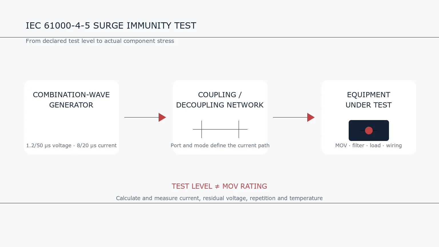
IEC 61000-4-5 is an electromagnetic compatibility (EMC) immunity test for equipment exposed to surge transients. It defines a repeatable laboratory method for applying unidirectional voltage and current surges associated with switching events and indirect lightning effects.
The standard is frequently mentioned beside metal-oxide varistors (MOVs), but it does not specify one universal MOV. The test is applied to complete equipment through defined ports, coupling networks and source impedances. The protection designer must translate that system-level requirement into stress at each component.

What the Standard Covers
IEC 61000-4-5 defines immunity test levels, test equipment, laboratory setups and procedures for electrical and electronic equipment. It addresses surges produced by switching transients and lightning-related effects. It is not intended to reproduce a direct lightning strike on equipment.
The applicable product or product-family standard normally decides which ports are tested, the required level, polarity, repetition, phase angle and performance criterion. IEC 61000-4-5 supplies the common test method; it does not assign the same requirement to every product.
The Combination-Wave Generator
The most familiar generator is called a combination-wave generator because its output is described differently under open-circuit and short-circuit conditions:
- 1.2/50 microsecond voltage waveform: the open-circuit voltage rises rapidly and then decays to half value over approximately 50 microseconds.
- 8/20 microsecond current waveform: the short-circuit current rises rapidly and decays to half value over approximately 20 microseconds.
These are generator calibration waveforms, not two independent events applied at the same time. Once the generator is connected to equipment, the actual voltage and current depend on the load and protection network.
Why Source Impedance Matters
A test voltage alone does not determine surge current. The effective source impedance limits the current available from the generator. The required generator configuration and coupling network depend on the port being tested, such as an AC power port, DC power port or signal line.
For a first-order estimate, an open-circuit voltage divided by source impedance gives an approximate short-circuit current. That simple calculation is not a substitute for the prescribed setup, because coupling components, line impedance, phase angle and the equipment’s nonlinear response affect the real waveform.
Line-to-Line and Line-to-Ground Tests
Differential-mode coupling applies the surge between conductors, for example line to neutral. Common-mode coupling applies it from one or more conductors toward protective earth or another reference.
These modes can produce very different current paths. A line-to-neutral MOV cannot automatically protect a line-to-earth path. The schematic, insulation system, protective-earth arrangement and applicable safety rules must be reviewed together.
What “Test Level” Really Means
A declared level describes the generator setting under the specified test configuration. It is not the voltage that every internal component must withstand and it is not the voltage that appears across the protected load after clamping.
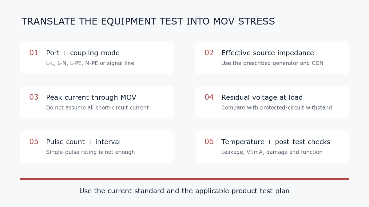
To evaluate an MOV, determine or measure:
- the coupling mode and effective source impedance;
- the current division among the MOV, filters, other suppressors and parasitic paths;
- the peak current and waveform through the MOV;
- the residual voltage at the protected node;
- the number, polarity and spacing of applied pulses;
- the initial temperature and cooling between pulses.
How to Relate the Test to an MOV Datasheet
Compare the estimated MOV stress with ratings stated under matching conditions. Important checks include maximum continuous AC or DC voltage, varistor voltage, maximum clamping voltage at a specified pulse current, repetitive-pulse capability, energy, temperature derating and temporary overvoltage behavior.
An MOV datasheet may quote an 8/20 microsecond peak-current rating, which is relevant to the combination-wave current shape. However, the largest single-pulse current is rarely the complete design criterion. Equipment tests apply multiple pulses, and the protected circuit must also remain within its acceptable voltage limit.
Pass Criteria Are System-Level
The product standard or test plan defines acceptable equipment behavior during and after the surge. Depending on the application, temporary performance degradation may be permitted, or continuous normal operation may be required. Safety must not be compromised.
A passed MOV component pulse test does not prove that the equipment will pass. Conversely, a complete product can pass because its impedance, filtering, shielding and coordinated protection reduce the stress on an individual suppressor.
Common Interpretation Errors
- Selecting an MOV only from the generator’s open-circuit voltage.
- Assuming the 8/20 short-circuit current all flows through one MOV.
- Ignoring whether the test is line-to-line or line-to-ground.
- Using a single-pulse maximum for a multi-pulse qualification sequence.
- Comparing clamping voltages measured at different currents or waveforms.
- Forgetting normal mains tolerance and temporary overvoltage when choosing MCOV.
- Treating IEC 61000-4-5 as a component certification or an SPD product standard.
Practical Pre-Test Checklist
- Identify the applicable product standard and exact port requirement.
- Record level, polarity, coupling path, phase angle, pulse count and interval.
- Draw the expected surge-current loop on the actual PCB and wiring diagram.
- Calculate an initial current estimate, then verify with suitable measurements.
- Check MOV current, residual voltage, temperature and post-test leakage.
- Coordinate fuses, thermal disconnects, gas discharge tubes, TVS diodes and filters where used.
- Define the functional and safety pass criteria before testing.
Frequently Asked Questions
Does a 2 kV test require a 2 kV MOV?
No. The 2 kV value is an open-circuit generator setting in a defined test. MOV selection depends on normal operating voltage, source impedance, surge current, residual voltage, pulse sequence and the protected circuit’s withstand level.
Is 8/20 microseconds an MOV energy waveform?
It primarily describes the impulse-current shape. Energy absorbed by the MOV depends on the simultaneous voltage across it and current through it over time.
Can one laboratory result be reused for a different cable or enclosure?
Not automatically. Cable routing, grounding, PCB layout and enclosure construction can change coupling and current paths. Follow the product standard’s rules for representative configurations.
Related UBAEC Guides
- MOV Surge Waveforms: 8/20, 10/1000 and Energy
- MOV Placement: Line-to-Line vs Line-to-Ground
- MOV Clamping Voltage Explained
- How to Select an MOV
Technical Reference
For a private review, send the port type, normal voltage, required surge level, coupling mode, source impedance and schematic through Ask UBAEC.












