

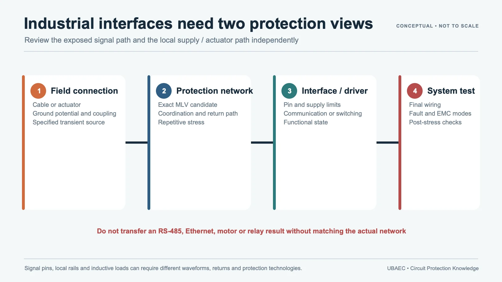
When current through a motor winding, solenoid or relay coil is interrupted, stored magnetic energy drives the voltage upward until a clamp, switch, arc or parasitic path absorbs it. An MLV can be placed across the load, switch or local rail, but the correct choice depends on energy, source impedance, clamp target, repetition, temperature and the operating behavior required from the actuator.
One successful turn-off pulse does not establish repetitive life. The same design may switch thousands or millions of times. Leakage and varistor-voltage drift, self-heating, cooling interval, PCB temperature and failure state must be part of release.
Capture the Real Switching Event
Start with supply voltage, coil resistance and inductance, steady-state/peak current, switch type, wiring, parasitic capacitance, switching rate, duty cycle, ambient/board temperature and required release or drop-out time. The initial magnetic-energy estimate is one-half L times current squared, but measured energy can differ because current decay, resistance, mechanical motion and other circuit paths change during release.
| Gate | Required evidence | Failure risk |
|---|---|---|
| Continuous voltage | Normal, tolerance, reverse/fault state and temperature | Leakage or heating while energized |
| Clamp window | Switch/load absolute maximum and exact MLV Vc/current/waveform | Device overstress or excessive residual voltage |
| Pulse energy | Measured current/voltage integral, duration and source impedance | 8/20 µs or 10/1000 µs rating misapplied |
| Repetition | Frequency, burst pattern, duty cycle, cooling and mission count | Progressive Vvar/leakage drift or thermal runaway |
| Function | Relay release, solenoid response, motor torque/noise and contact stress | A “safer” low clamp changes actuator behavior |
Use the parameter and test-condition guide. TDK’s surge-selection method requires peak voltage, pulse width, DC bias, repetition period/count and source resistance. KYOCERA AVX TransGuard and Eaton MLVC tables attach Vc current, 8/20 µs peak current and 10/1000 µs energy to exact models. Do not combine these conditions.
Choose Placement and Clamp Behavior Together
A clamp across the coil localizes current and protects the switch path. A clamp across the switch limits switch voltage but can route energy through the supply/ground structure. A rail clamp may protect several loads but must absorb combined events and coordinate with capacitance, regulator and upstream protection. Layout parasitics can create an overshoot beyond the nominal clamp.
Compare a flyback diode, TVS, MLV and RC snubber by operating consequence. A low-voltage diode often gives slow current decay and longer relay/solenoid release. A higher-voltage clamp can speed release but increases switch and insulation stress. RC behavior depends on frequency and values. MLV clamp and energy capability are nonlinear and exact-part specific. Use the MLV versus TVS comparison; there is no universal winner.
Use Application Evidence Within Its Scope
TDK identifies repeated counter-electromotive-force use for selected chip-varistor products and provides a tool for repeated surge evaluation. Its “optimal applications” page is manufacturer comparison evidence, not a neutral ranking; its graphs and product suggestions remain supplier- and test-specific. KYOCERA AVX lists motor/inductive-load transient suppression for TransGuard Automotive, while Eaton MLVC states high-energy use for EFT and inductive-load switching. These are candidate families, not automatic substitutes.
Panasonic’s performance/test table separates 8/20 µs surge tests, interval/count and IEC 61000-4-2 ESD conditions by series. Eaton’s January 2021 MLVC sheet likewise separates 1 mA DC varistor voltage, model-dependent clamp current, 8/20 µs peak current, 10/1000 µs energy and typical capacitance at 1 MHz. These sources reinforce the method: retain the exact order code, waveform and acceptance. Apply the selection workflow and the reliability guide.
Validate Repetitive and Fault Behavior
Release time is a protection variable, not only a mechanical detail. A relay held longer can change contact arcing or control timing; a solenoid released too quickly can create impact, acoustic or process effects. For motors and stepping actuators, the clamp can affect current decay, torque and EMI. Capture these outcomes beside electrical stress.
If several loads share a rail clamp, test coincident and staggered switching. Combined energy, rail rise and regulator interaction can exceed the result from one channel. A local across-coil clamp and a shared rail clamp therefore require different mission-profile evidence even when they use the same nominal device.
- Measure coil/load voltage and current at worst supply, temperature and mechanical state.
- Measure switch voltage, clamp current, energy and release/drop-out time.
- Run the mission-profile repetition and burst pattern with realistic cooling.
- Monitor MLV/PCB/switch temperature and check function during testing.
- Measure leakage, Vvar, clamp response and physical condition before and after stress.
- Test open/short MLV, stalled load, welded contact, blocked actuator and fuse/current-limit behavior as required.
Use the layout guide to control the high-current loop. If the load is part of a PLC output module, link the port requirements to the PLC/industrial-I/O guide. Keep cabinet or mains surge separate from local DC switching.
Alternate and Construction Boundary
An alternate must match construction, package, termination, working voltage, Vvar/test current, clamp/current, energy/waveform, repetitive data, leakage, capacitance, temperature and lifecycle. Use the cross-reference method. Review the MLV/MOV construction boundary before applying disc- or molded-MOV evidence to a multilayer chip device.
Minimum Inquiry Data
- load type, supply, coil resistance/inductance/current and mechanical release requirement;
- switch limits, measured waveform, source resistance and parasitic layout;
- event frequency, burst pattern, duty cycle, lifetime count and temperature;
- preferred clamp location and diode/TVS/RC/MLV alternatives;
- package, qualification, lifecycle, fault state and acceptance criteria.
Summary
Inductive-load protection is selected from the measured energy, clamp window, repetition and required actuator behavior. Approve an MLV only as an exact part in the final switching circuit after endurance, thermal, functional and fault testing.
Use the MLV Technical Resources & Datasheet Library or return to the MLV Knowledge Map.
Continue Reading
- DC Power and LED Module Protection with MLVs
- MLV vs SMD MOV and Disc MOV
- MLV Reliability, Standards and Failure Modes
- MLV PCB Layout, Mounting and Soldering Reliability
Official Technical References
The following first-party, standards-organization or publisher records support the technical boundaries used in this article. Always verify the current revision and the exact product scope before design release.












