

A DC LED module can be damaged by connector ESD, cable-induced spikes, driver switching events, wiring interruption or a transient coupled from an upstream supply. These events do not all have the same source impedance, duration or energy. An MLV can be a compact local shunt device, but only after the protected node and transient are measured.
First separate the AC installation boundary from the local DC board. A small board-level MLV on an LED output is not automatically an AC-mains surge protective device. The input fuse, insulation, creepage and clearance, coordinated SPD or MOV, driver isolation and safety requirements remain separate engineering controls. The dedicated AC-input and high-energy boundary guide remains held for specialist safety review, so no mains-side technology decision should be inferred from this page.
Locate the Protection Boundary
| Node | Typical concern | Release question |
|---|---|---|
| AC input | Installation surge, temporary overvoltage, fault current and safety | Is a certified, coordinated upstream protection stage required? |
| DC input rail | Adapter/cable transient, hot plug, reverse connection and switching overshoot | What voltage, source impedance, duration and repetition reach the board? |
| Driver output | Open-load behavior, cable inductance and switching edges | What clamp window preserves the driver and LED regulation? |
| Remote LED board | User or connector ESD and local wiring spikes | Where can current be diverted without crossing the protected circuit? |
Begin with the MLV Knowledge Map and the parameter and test-condition guide. Record the normal rail, tolerance, ripple, start-up and fault states before selecting a continuous working voltage. V1mA or another breakdown value is not the allowed DC rail by itself.
Keep Every Rating with Its Test Condition
A current KYOCERA AVX TransGuard document illustrates why column names alone are unsafe. It lists DC and AC working voltage, typical breakdown voltage at 1 mA DC, clamping voltage at a stated current, leakage at working voltage, transient energy using a 10/1000 µs waveform, peak current using 8/20 µs and capacitance at a stated frequency and amplitude. The exact order-code row and its definitions form one evidence unit.
Do not compare an 8/20 µs peak-current value directly with a 10/1000 µs energy value. Do not use a clamp voltage without its test current. Also check temperature derating, tolerance, leakage after stress, soldering and mechanical condition. The MLV selection workflow keeps these gates in sequence.
What LED Evidence Does and Does Not Prove
TDK reports an actual-equipment experiment in which an LED remained operating through the stated IEC 61000-4-2 contact-discharge sequence when a listed chip varistor was used. This supports the feasibility of local LED ESD protection under that enclosure, board, strike and part configuration. It does not establish switching-surge energy, repetitive lifetime or suitability for every LED driver.
For a DC rail or long cable, capture voltage and current at the connector, MLV and protected node. Calculate energy only from the measured waveform or a defensible source model. Repetition matters: a part that survives one pulse can accumulate heating or parameter drift during bursts and the application mission profile. Use the reliability and failure-mode guide.
High-Voltage MLVs Are Exact-Model Exceptions
Some manufacturers offer high-voltage multilayer varistors for power, network and LED applications. Sunlord’s SVMH document, for example, provides model-specific AC/DC working values, varistor voltage, clamp conditions, 8/20 µs peak current and 10/1000 µs energy. That evidence applies only to the listed size and order code. A high value in one 2220 row cannot be transferred to smaller sizes or to a generic “MLV” claim.
INPAQ’s MLVS HV page identifies industrial LED and GFCI applications and public certification statements, but it directs users to contact the company for detailed support. Until a current detailed datasheet is available, UBAEC should not publish numeric selection limits from that page. Compare construction boundaries in MLV versus SMD MOV and disc MOV.
Coordinate the Protection Stack
The most suitable solution may combine a fuse or current limiter, AC-input MOV/SPD, TVS diode, local MLV, RC snubber, EMI filter, grounding and mechanical shielding. The correct combination depends on fault current, transient duration, residual-voltage window, leakage, capacitance, available space and failure behavior. Use the MLV versus TVS diode comparison; there is no universal winner.
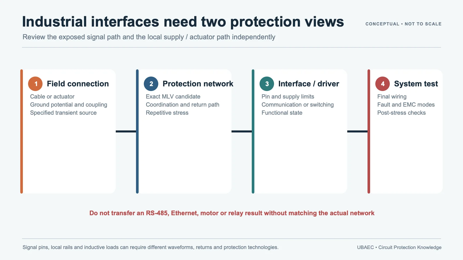
If a relay, solenoid or motor shares the supply, perform a separate inductive-load review. Its release-time and repetitive-energy questions differ from LED ESD, and the dedicated guide is not linked until its publication review is complete. Keep the transient return path short and controlled using the layout, mounting and soldering guide.
Final Driver and Module Validation
- Capture normal, start-up, shutdown, open-load, hot-plug and fault voltages across temperature.
- Define ESD or surge generator, coupling path, source impedance, polarity, pulse count and interval.
- Measure current through the candidate and residual voltage at the driver and LED.
- Check regulation, flicker, dimming, communication and restart behavior during and after stress.
- Run repetitive and thermal tests for the actual event rate; inspect leakage, V1mA drift and physical condition.
- Repeat on the final PCB, cable, enclosure, connector, driver firmware and production alternate.
IEC 61000-4-5 defines equipment surge testing; it does not turn a component rating into final-equipment compliance or direct-lightning capability. Release requires the final driver and module result.
Minimum Inquiry Data
- AC/DC boundary, topology, isolation state and protected node;
- rail voltage, tolerance, ripple, fault and open-load limits;
- transient waveform, source impedance, repetition and temperature;
- required clamp window, leakage, capacitance, package and failure response;
- exact candidate order code and final PCB/cable/enclosure test plan.
Summary
Use an MLV on a DC rail or LED module only when the exact voltage, clamp, energy, repetition and thermal evidence fits the measured event. Keep AC installation protection and model-specific high-voltage exceptions visible.
Consult the MLV Technical Resources & Datasheet Library or return to the MLV Knowledge Map.
Continue Reading
- Motor, Solenoid and Relay Transient Protection with MLVs
- MLV Datasheet Parameters and Test Conditions
- MLV Reliability, Standards and Failure Modes
- How to Select an MLV: A Practical Engineering Workflow
Official Technical References
The following first-party, standards-organization or publisher records support the technical boundaries used in this article. Always verify the current revision and the exact product scope before design release.
- Example of ESD Countermeasures on Actual Equipment: LED Protection with Chip Varistors
- TransGuard multilayer ceramic transient voltage suppressors datasheet
- Chip Varistor for Surge Suppression – SVMH Series
- MLVS HV Series product page
- IEC 61000-4-5:2014+AMD1:2017 CSV – Electromagnetic compatibility (EMC) – Part 4-5: Testing and measurement techniques – Surge immunity test











