

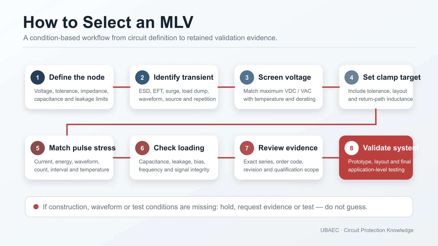
An MLV cross-reference is not a search for the same package and nominal varistor voltage. Two parts can look similar while differing in construction, topology, continuous voltage, clamp-test current, pulse waveform, capacitance, temperature, qualification or lifecycle.
A cross-reference produces a candidate for validation, not a drop-in guarantee. The method below compares exact current order codes, preserves every material discrepancy and records what still requires supplier confirmation or testing.
Three Possible Outcomes
| Outcome | Meaning | Next action |
|---|---|---|
| Reject | A hard constraint such as construction, topology, voltage, package, temperature or qualification fails | Do not proceed as an alternate |
| Conditional candidate | Required fields appear compatible, but one or more values, conditions, revisions or tests remain unresolved | Obtain evidence and validate before approval |
| Validated alternate | Exact evidence and the applicable engineering, production and system tests have passed for the defined use | Approve only within the documented scope and revisions |
“Same series,” “equivalent,” “replacement” or “cross” in a distributor table is discovery input only. It does not change these gates.
Step 1 — Lock the Reference Part and Application
Record the original manufacturer, full order code, datasheet revision, lifecycle state and the actual circuit position. Capture normal rail, tolerance, abnormal voltage, transient source, protected-node limit, signal bandwidth, temperature range, package/assembly constraints and required qualification.
If the original part’s application conditions are unknown, first reconstruct the design requirement. An alternate cannot be validated against an undefined target.
Step 2 — Verify Construction and Topology
Confirm that both devices are construction-confirmed ceramic MLVs. Do not substitute a molded SMD MOV, disc MOV, resin/polymer suppressor or ambiguous SMD varistor because the package or voltage looks similar.
For multi-terminal devices, draw the exact internal topology. An independent array, shared-common array, differential 2-in-1 part and feedthrough/filter device are not interchangeable. The terminology guide and array/topology guide own these boundaries.
Step 3 — Match Package, Termination and Assembly
Compare body dimensions, height, terminal layout, land pattern, orientation, termination material/finish, solder process, cleaning limits, board-flex sensitivity and storage/handling requirements. A nominal 0603 or 1206 size does not prove identical geometry or assembly behavior.
If the land pattern or current path changes, review the PCB rather than forcing a mechanical substitution. Use the MLV layout, mounting and soldering guide.
Step 4 — Translate Every Electrical Field
| Field | Required evidence | Reject or hold trigger |
|---|---|---|
| VDC/VAC | Maximum continuous rating, temperature/derating and rail margin | Rating too low, wrong AC/DC basis or unspecified derating |
| Vvar | Min/nom/max, test current, polarity, tolerance and temperature | Different test current or range not compatible |
| Vc | Clamp voltage, injected current, waveform, tolerance and temperature | Unmatched current/waveform or clamp budget exceeded |
| Imax | Peak current, waveform, pulse count, interval and acceptance criteria | Clamp-test current confused with Imax or duty unsupported |
| Energy | Value plus waveform/pulse duration, repetition and temperature | 10/1000 µs, 2 ms or unstated methods mixed |
| Capacitance | Maximum/typical status, frequency, amplitude, DC bias and temperature | Mixed 1 kHz/1 MHz data or signal budget exceeded |
| Leakage | Limit at a defined voltage and temperature | Unmatched bias point or standby-current failure |
| ESD/dynamic clamp | Generator/network, polarity, mode, shots, fixture and measured node | Surge Vc substituted for ESD clamp or system result inferred |
The MLV parameter and test-condition guide defines these fields. A missing value stays missing; never fill it with zero, a family maximum or data from another package.
Step 5 — Match Temperature, Reliability and Qualification
Compare operating and storage range, derating, humidity and mechanical tests, pulse/lifetime evidence and stated failure criteria. Match qualification to the exact order code, termination, temperature grade and declared revision. A family heading or AEC-Q200 logo does not prove every order code has the same scope.
Component qualification, system immunity and mission-profile validation are separate evidence layers. See MLV reliability, standards and failure modes.
Step 6 — Verify Source, Revision and Lifecycle
Use the current exact manufacturer datasheet for numeric decisions. A product hub or selection guide can map the family, while a distributor page, mirror, search result or archived PDF may help discovery. None should silently override the exact current source.
Record the retrieval date and any filename/body, page/PDF, regional or lifecycle conflict. Navigation absence is not blanket end-of-life evidence, and a portfolio maximum is not a realizable combined order code. Use the MLV manufacturer research map for dated family/lifecycle discovery and the MLV Technical Resources & Datasheet Library for controlled source routes; current exact first-party datasheets still govern numeric decisions.
Step 7 — Build a Discrepancy Log
Do not hide differences inside a single pass/fail cell. For each field, record the original value and conditions, candidate value and conditions, evidence URL/revision, comparison state, risk and required action.
| State | Use | Example action |
|---|---|---|
| Green — evidenced match | Definitions and conditions align and the candidate meets the requirement | Carry to validation |
| Yellow — conditional | Difference may be acceptable but needs calculation, confirmation or test | Assign owner and closure evidence |
| Red — incompatible | Hard requirement fails or technology/topology differs | Reject candidate |
| Grey — unknown | Controlling data is absent, conflicting or not current | Hold; request supplier evidence |
Unknown is not the same as zero, not applicable or acceptable. Every yellow and grey item needs an owner, next action and release condition.
Step 8 — Check the Complete Protection Architecture
An alternate can change clamp voltage, capacitance, leakage, current distribution and failure behavior even when the individual datasheet fields look close. Recheck coordination with series impedance, filters, TVS devices, fusing, upstream surge protection, protected-IC limits and the transient return path.
Apply the MLV selection workflow to the candidate as a new design decision rather than treating the cross-reference as a clerical substitution.
Step 9 — Validate Engineering and Production
Test the exact candidate on the representative PCB with the required transient/ESD generator, source impedance, polarity, event sequence, temperature and acceptance criteria. Measure the protected-node waveform and check signal integrity where relevant.
Also validate assembly: solderability, reflow/flow profile, placement, inspection, board flex, cleaning and production yield. Keep the candidate order code, lot, PCB revision, equipment setup and results with the approval record.
Minimum Inquiry Data for a Cross-Reference Review
- original full order code and current datasheet;
- circuit/function and schematic location;
- normal and abnormal voltage range;
- transient source, waveform/network, peak, source impedance and repetition;
- maximum acceptable clamp voltage at the protected node;
- capacitance/leakage/signal-bandwidth constraints;
- package, land pattern, temperature, qualification and lifecycle requirements;
- required engineering, EMC, reliability and production tests.
Summary
A safe MLV cross-reference is an evidence-controlled engineering change. Match construction and topology first, then package, voltage definitions, clamp conditions, pulse duty, capacitance, leakage, temperature, qualification and lifecycle. Log every discrepancy and approve the alternate only after exact-device PCB and system validation.
Return to the MLV Knowledge Map or Ask UBAEC with the original part, application conditions and required validation scope.
Continue Reading
- MLV Datasheet Parameters and Test Conditions
- How to Select an MLV: A Practical Engineering Workflow
- MLV Manufacturer and Product-Family Research Map
- MLV Technical FAQ: Parameters, Selection and Reliability
Official Technical References
The following first-party, standards-organization or publisher records support the technical boundaries used in this article. Always verify the current revision and the exact product scope before design release.
- Catalog: Chip Varistors / Ceramic Transient Voltage Suppressors
- TransGuard multilayer ceramic transient voltage suppressors datasheet
- ZVE Series Suppression Varistors datasheet
- MLVC high energy multilayer varistor datasheet
- NXED Transient Voltage Suppressor Datasheet
- Automotive multilayer varistors EZJZ-M, EZJP-M and EZJPR-M 2-in-1












