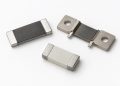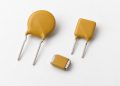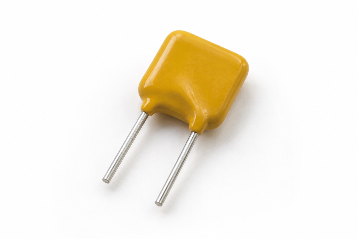
A polymeric positive-temperature-coefficient device (PPTC) is often described with a hold current, Ihold, and a trip current, Itrip. Those two numbers can look like the lower and upper thresholds of an ideal switch. They are not. A PPTC changes state through self-heating, so current is only one part of the operating condition; ambient temperature, copper area, enclosure airflow, fault duration, and previous trips all affect the result.
The engineering task is therefore not to find one magic current. It is to show that the device remains low resistance during every legitimate load, trips soon enough for the weakest credible fault, limits the post-trip condition safely, and resets acceptably after power and temperature have fallen.
What Ihold and Itrip actually establish
Ihold is generally the highest steady current that the device can carry without transitioning to its high-resistance state under the manufacturer’s stated ambient and test conditions. It is a normal-operation check, not a promise that the same current can be carried indefinitely in every PCB and enclosure. Manufacturers publish hold-current derating versus ambient temperature because less additional self-heating is required as the surroundings become hotter.
Itrip identifies a current that will drive the device toward its high-resistance state under specified conditions. It does not say that the transition is instantaneous. Trip time depends strongly on fault current: a large multiple of rated hold current may trip quickly, while a current close to the boundary may take much longer. A load that can tolerate only tens of milliseconds may be damaged even though the selected PPTC eventually trips.
Why the region between them is not a guaranteed switch point
A useful physical model compares electrical heating, approximately I²R, with heat transferred to the environment. At low current, the device settles at a low-temperature, low-resistance equilibrium. As current or ambient temperature rises, heating can push the polymer through a steep resistance increase. Between the specified hold and trip regions, the final state can depend on time and thermal conditions; a single room-temperature table cannot resolve it.
PCB copper area, pad geometry, nearby hot components, potting, airflow, and enclosure temperature all change heat loss. The same catalog part can behave differently on a manufacturer’s test fixture and in a compact product. Littelfuse therefore recommends applying thermal derating and independently testing suitability in the real application.
A practical four-step datasheet method
1. Lock the ambient condition
Record the temperature used for Ihold, Itrip, and time-to-trip data, then apply the manufacturer’s derating information at the highest local ambient expected near the device. Do not apply a 23 °C or 25 °C hold-current value directly inside a 70 °C enclosure. Maximum operating temperature is also not a statement that the room-temperature current rating remains available at that limit.
2. Separate normal load from fault current
Define continuous load current, allowed peaks, startup or charging inrush, duration, and repetition. Separately define the minimum fault current that must be cleared, maximum circuit voltage, and maximum available short-circuit current. Verify Vmax and Imax for the exact series; a PPTC selected only by Ihold can be outside its voltage or interruption boundary.
3. Use the time-to-trip curves
At the weakest credible fault, read the manufacturer’s typical time-to-trip curve and compare that time with the thermal withstand of the connector, trace, cable, battery, and load. Typical curves are not guaranteed worst-case limits. Component tolerance, supply variation, and temperature margin must be covered by specified limits where available and by application testing.
4. Check the post-trip and reset states
A tripped PPTC is a hot high-resistance limiter, not an open contact. Residual current, voltage across the device, its power dissipation, surface temperature, and the downstream circuit’s state must all be safe while the fault remains. After the fault is removed, current normally has to fall sufficiently and the part must cool. Its resistance may remain above the initial value for some time, which is why selection guides call attention to post-trip resistance such as R1max.
A bounded example
Consider a product with 0.45 A continuous load, a 1.2 A startup pulse lasting 80 ms, a maximum local ambient of 60 °C, and a weakest fault of only 1.0 A. The correct selection is not simply any part whose room-temperature Ihold exceeds 0.45 A and whose Itrip is below 1.0 A. First check the 60 °C derated hold current. Then place the startup pulse on the time-current information to prevent nuisance trips. Finally confirm that 1.0 A trips before the protected element exceeds its safe time-temperature boundary.
If the minimum fault sits too close to the thermally derated hold region, the PPTC may remain hot for an extended time without reducing current enough. The remedy may be a different PPTC, tighter source current limiting, or a different protection architecture—not an assumption that Itrip is an instantaneous cutoff.
PPTC versus a one-time fuse
Resettable operation is useful, but it does not give a PPTC the same clearing behavior, approvals, or failure modes as a conventional fuse. Where available fault current, fire containment, isolation, or an equipment standard governs the design, determine separately whether a certified fuse or another disconnect is required. Likewise, a line fuse does not automatically replace an MOV’s local thermal disconnect; the two respond to different hazards, as explained in fuse and MOV thermal-disconnect coordination.
What to verify on hardware
Test minimum and maximum input voltage, the hottest ambient, hot restart, minimum and maximum fault impedance, repeated faults, and the intended reset interval. Record current, PPTC voltage, trip time, and temperature. Recheck normal voltage drop after recovery. If the design also uses an NTC inrush limiter, keep its cold and hot states separate using the method in NTC cold resistance versus steady-state voltage drop.
For background, a PPTC is a nonlinear resistive device whose resistance is strongly temperature dependent; linear versus nonlinear resistors provides the classification context. A broader electronic-component function map helps confirm that current limiting, overvoltage protection, and thermal disconnection have not been assigned to one part without evidence.
FAQ
Is Itrip a precise guaranteed trip threshold?
No. It is tied to the manufacturer’s stated conditions, while the transition also depends on time and the thermal environment. Use time-to-trip information and hardware testing.
Will current below the room-temperature Ihold always avoid a trip?
No. High ambient temperature, nearby heat sources, and restricted cooling reduce available hold current. Startup and repetitive peaks also matter.
Does a tripped PPTC completely remove power?
Usually not. It limits current in a high-resistance state, so residual current and power must be evaluated for the system.
Does resistance immediately return to its initial value?
Not necessarily. Cooling takes time, and post-trip resistance can remain higher than the initial resistance. Check the exact series data and reset conditions.
Conclusion
Ihold establishes a normal-use boundary and Itrip helps describe a trip region, but together they do not form one ideal switching threshold. A defensible design combines ambient derating, layout thermal effects, time-to-trip behavior, Vmax, Imax, residual post-trip operation, and recovery resistance in one test plan.
References: Littelfuse, Fundamentals of Resettable Functionality in PPTC Devices; Littelfuse POLYFUSE PTC Selection Guide.