

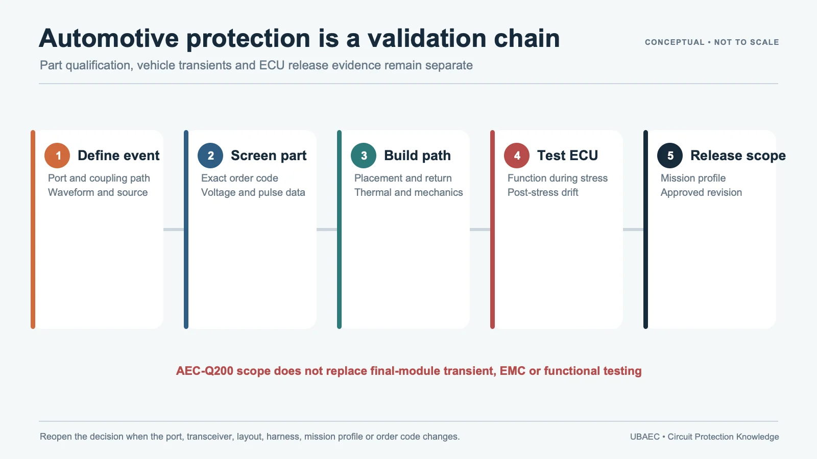
Load dump is not a larger version of an 8/20 µs surge. A longer automotive pulse can deposit much more energy, heat the suppressor and change its clamp behavior even when the peak current looks modest.
Only an exact MLV with explicit long-pulse or load-dump evidence should enter this design path. It may be the primary clamp for a documented condition or a secondary element coordinated with an upstream TVS/MOV, current limiting, fuse and thermal/fault containment.
Lock the Generator and Vehicle Condition
Record the applicable ISO/OEM/customer pulse, open-circuit voltage, source impedance, rise/decay or duration, repetition, interval, supply state, polarity, temperature and functional criterion. Jump start, reverse battery, load dump and short switching pulses are separate conditions.
ISO 7637-2 is a module-level supply-line framework. A component table that references a pulse does not prove the ECU passes that standard. Use the MLV reliability and standards guide to keep the test object and edition visible.
Do Not Exchange Waveforms
| Datasheet field | What it can support | What it cannot prove |
|---|---|---|
| Imax at 8/20 µs | Short peak-current capability under stated pulse count/interval | Load-dump energy or long-pulse temperature |
| Energy at 10/1000 µs | Energy capability under that specified waveform | Another duration or generator without analysis/test |
| WLD/load-dump field | Named part under the supplier’s load-dump method | Every order code, standard revision or ECU setup |
| Vjump | Supplier-defined jump-start voltage/time condition | Continuous operating voltage or load-dump clamp |
Littelfuse AUML, KYOCERA AVX automotive TransGuard, the KEMET-branded VA document and Eaton AMLV sources all keep these fields separate. AUML also defines varistor voltage at 10 mA rather than the 1 mA common in many MLV tables. Translate each definition with the parameter and test-condition guide.
Calculate the Stress Seen by the Exact MLV
Use the source network and complete protection circuit to determine suppressor current, clamp voltage, absorbed energy and temperature. Do not compare generator voltage directly with a component Vc row. Include wiring/series impedance, upstream clamp, fuse, supply and protected-load behavior.
Check pulse-to-pulse cooling, ambient/underhood temperature, enclosure airflow, PCB copper and nearby heat sources. Repeated events can cause leakage or varistor-voltage drift before visible damage. A one-shot pass is not repetitive-life evidence.
Choose a Coordinated Architecture
A local MLV may protect a secondary rail or reduce residual voltage after an upstream stage. A larger exact MLV may handle a documented module pulse. In either case, coordinate:
- upstream TVS, MOV or vehicle-level suppression;
- series resistance, harness/source impedance and current limiting;
- fuse or thermal protection and abnormal-overvoltage behavior;
- protected IC/DC-DC limits and downstream capacitance;
- expected failure state, fault current and containment.
The related 12 V, 24 V and 48 V local-rail guide owns the rail-selection workflow. The MLV selection guide owns the exact-part evidence gates.
Keep Product Claims Exact
KYOCERA AVX publishes load-dump energy and pulse-duration/source-resistance information by order code. Its separate 2,000 A announcement applies to listed 2220 parts and does not create a family-wide value. The KEMET-branded VA document, now carrying YAGEO Group disclaimer language, separates 10/1000 µs Wmax from WLD. Eaton separates Vjump, WLD, leakage and model-specific clamp current. These distinctions must remain in any comparison.
Do not silently modernize a supplier’s test basis. The current KYOCERA AVX TransGuard Automotive Rev 4 PDF still cites ISO 7637-2-2004 and older load-dump terminology. ISO lists ISO 7637-2:2011 as current and confirmed in 2025. A value from the supplier PDF therefore remains evidence for its stated method and order code, not proof that the part or ECU satisfies every requirement of the later edition.
AEC-Q200 or another passive qualification is not load-dump or vehicle compliance. Confirm the exact order code, package, termination, temperature grade, lifecycle and current datasheet revision.
Minimum Validation Plan
- Measure module input, MLV current and protected-node voltage under the exact generator/source impedance.
- Monitor suppressor and PCB temperature during and between pulses.
- Repeat the required pulse count at worst-case supply, load and ambient conditions.
- Check function during the event and leakage, Vvar, clamp and physical condition afterward.
- Test jump-start, reverse/abnormal states and fault coordination separately where required.
- Retain part lot, PCB revision, setup, waveforms, temperature records and acceptance results.
Review footprint, soldering and thermal/mechanical controls in the MLV layout and assembly guide. An alternate part must pass the MLV cross-reference method and the same module tests.
Minimum Inquiry Data
- vehicle or module rail, normal voltage range, jump-start and reverse-battery states;
- applicable ISO, OEM or customer pulse, edition, generator voltage, source impedance, duration, polarity, count and interval;
- module load, protected-device limits, upstream suppression, fuse/current limiting and expected clamp target;
- ambient/board temperature, enclosure, PCB copper, cooling and permitted temperature rise;
- candidate order code, package, qualification, lifecycle, expected failure state and module acceptance criteria.
Record a Scope-Limited Decision
The release record should name the MLV order code, datasheet revision, PCB and module revision, pulse plan, upstream devices, source impedance, ambient condition and accepted number of events. Classify the result as rejected, conditional pending evidence or validated only for the tested architecture.
Reopen the decision when the alternator/vehicle network, pulse edition, source resistance, upstream suppressor, fuse, enclosure, PCB copper, MLV lot or protected load changes materially. A part that passed as a secondary clamp cannot be promoted to the primary load-dump element without new energy and fault analysis.
Summary
Load-dump and long-pulse protection is an energy, temperature and coordination problem. Preserve the exact generator, source impedance, duration, repetition and acceptance criteria; use only explicit exact-part evidence; and approve the architecture after measured final-module testing.
Use the MLV Technical Resources & Datasheet Library, return to the MLV Knowledge Map, or ask UBAEC with the pulse plan and schematic.
Continue Reading
- 12 V, 24 V and 48 V Automotive Local-Rail MLV Protection
- MLV vs SMD MOV and Disc MOV
- MLV Reliability, Standards and Failure Modes
- How to Select an MLV: A Practical Engineering Workflow
Official Technical References
The following first-party, standards-organization or publisher records support the technical boundaries used in this article. Always verify the current revision and the exact product scope before design release.
- AUML Series Varistor Datasheet
- TransGuard Automotive Series multilayer varistors datasheet
- KEMET-branded VA Automotive Grade 125°C Surface Mount Varistors, with YAGEO Group disclaimer
- ISO 7637-2:2011 – Road vehicles – Electrical disturbances from conduction and coupling – Part 2: Electrical transient conduction along supply lines only
- AMLV automotive grade multilayer varistor datasheet











