

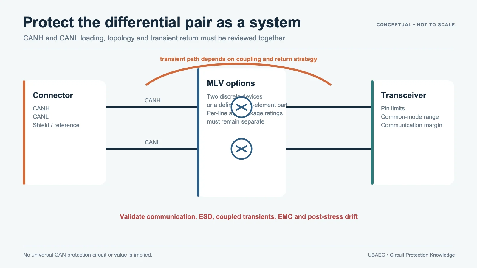
CAN protection is not solved by placing any two varistors beside the transceiver. The protection parts become part of a differential network: their capacitance, balance, leakage, clamp behavior, topology, placement and return path can affect both transient current and communication quality.
An MLV can be a useful CAN or CAN FD protection element when the exact device fits the bus and the complete module is validated. The design still has to coordinate the connector, common-mode choke or other filtering, termination, transceiver limits, ground or chassis strategy and the applicable vehicle test plan.
Start with the Threat and the Protected Node
Separate the events that the ECU must survive. Connector or harness ESD, coupled transients on signal wiring, powered-state disturbances and bulk-current-injection or other EMC exposure are different tests. They do not share one universal voltage, waveform, source impedance or acceptance criterion.
Define the protected node at the transceiver pins, not only the nominal generator setting. Record the CANH/CANL common-mode range, maximum permitted node voltage, normal and abnormal supply states, harness and connector configuration, operating temperature and whether the module is powered or unpowered during each event.
A component datasheet may report an 8/20 µs clamping voltage, an IEC 61000-4-2 component test or a peak-current value. These are useful inputs, but none alone proves the final ECU will pass an ISO 10605 or customer-specific module test. The MLV reliability and standards guide explains the evidence layers.
Choose the Protection Topology Before the Part Number
Two common MLV approaches are separate devices on CANH and CANL, or a multi-element device that integrates both protection elements. The correct reference node and routing depend on the transceiver and module grounding architecture; they must be shown explicitly in the schematic.
| Approach | Potential advantage | Main design control |
|---|---|---|
| Two discrete MLVs | Flexible sourcing, placement and per-line selection | Capacitance, tolerance, routing and current paths must remain sufficiently balanced |
| 2-in-1 or matched multi-element MLV | Integrated geometry and a supplier-defined relationship between the two elements | Confirm the internal circuit, per-line/package ratings, common terminal if any and exact matching specification |
| Array or feedthrough-style part | May combine multi-line suppression with a defined filtering behavior | Verify element independence, feedthrough current, S-parameters, land pattern and simultaneous-channel conditions |
Two discrete parts are not automatically equivalent to a matched 2-in-1 device. Conversely, an integrated package is not automatically better for every design. Compare the exact topology and evidence using the MLV array and topology guide.
Why Capacitance Balance Matters
CAN is differential. Unequal shunt capacitance and unequal interconnect parasitics can convert part of a differential signal into common-mode content or change the two line edges differently. CAN FD generally leaves less room for an unexamined protection network than a slower implementation, but the allowable loading belongs to the actual transceiver, bit timing, harness and EMC design.
Do not compare a nominal capacitance from one device with a maximum value from another. Retain measurement frequency, amplitude, DC bias, temperature, tolerance and whether the value is typical or guaranteed. Also inspect insertion loss, impedance or time-domain behavior when the supplier provides it. The parameter and test-condition guide owns these definitions.
One current manufacturer example illustrates why exact-device scope matters: Panasonic reports a 2-in-1 order code with 15 pF ±3 pF at 1 MHz and a maximum 1.0 pF difference between its two elements. Those figures belong to that named product and its stated conditions; they are not a generic limit for all multi-element MLVs or for two unrelated discrete parts.
Translate the Electrical Ratings Correctly
| Selection field | What to retain | Common error |
|---|---|---|
| Continuous voltage | VDC/VAC basis, CANH/CANL common-mode range, abnormal state and temperature margin | Selecting only from nominal bus voltage |
| Varistor voltage | Minimum/nominal/maximum, test current and tolerance | Treating V1mA as a working or clamp voltage |
| Surge clamp | Clamping voltage with injected current, waveform and temperature | Comparing values measured at different currents |
| ESD response | Generator network, polarity, contact/air method, shots, fixture and measured node | Substituting surge Vc for dynamic ESD clamp |
| Pulse capability | Waveform, peak, duration, repetitions, interval, temperature and acceptance | Inferring coupled-transient or long-pulse immunity from one 8/20 µs value |
| Capacitance and leakage | Per-line value, matching/balance, frequency/bias and leakage test point | Ignoring asymmetry or protected-state current |
Use the engineering MLV selection workflow for each exact order code. A family application diagram is a discovery aid; its table maximums must not be combined into a fictional part.
Coordinate the Whole CAN Interface
The MLV is only one current-diversion path. Review its position relative to the connector, optional common-mode choke, termination and transceiver. A low-inductance path to the intended reference is normally more important than an arbitrary millimetre rule. Keep the surge path away from protected traces and do not route discharge current through a narrow logic-ground detour.
A common-mode choke addresses a different noise mechanism and is not replaced automatically by a varistor. Likewise, an MLV does not replace transceiver-internal protection, correct termination, shielding or upstream power-rail protection. The final network has to work in both normal communication and each fault or immunity state.
Review land pattern, soldering, board flex and termination requirements with the MLV layout and assembly guide. Package integration can reduce component count, but it can also change routing, inspection and failure containment.
Qualification Is Not CAN Compliance
AEC-Q200 language applies only to the supplier-declared component and order-code scope. It does not prove CAN or CAN FD protocol conformance, ECU immunity, vehicle compliance or fitness for a particular mission profile. Confirm temperature grade, termination, package, revision and any documented qualification matrix.
Keep ISO 10605 automotive ESD, ISO 7637-3 coupled-transient testing and OEM test plans separate from component qualification. Record the test object, network, severity, operating mode and functional acceptance criterion beside every result.
Minimum Validation Plan
- Bench electrical review: verify continuous voltage, leakage, protected-node clamp and current sharing at relevant temperatures.
- Signal-integrity review: measure CANH/CANL symmetry, edge shape, common-mode behavior, jitter or eye-related margin with the exact transceiver, bit timing, harness and termination.
- ESD test: run the applicable ISO 10605 or customer plan at the actual connector points, polarities, powered states and discharge counts.
- Coupled-transient and EMC tests: apply the required harness-coupling and BCI or related tests without treating a supplier demonstration as a module guarantee.
- Post-stress checks: inspect communication faults, leakage, varistor-voltage drift, clamp behavior, temperature and physical damage.
- Production review: verify placement, soldering, inspection and lot/board-revision traceability.
If an alternate MLV is proposed, repeat the comparison and validation. The MLV cross-reference method records exact conditions and unresolved discrepancies.
Design Information to Collect
- CAN or CAN FD implementation, data phase and transceiver order code;
- normal and abnormal CANH/CANL voltage and common-mode range;
- connector, harness, termination, choke/filter and reference strategy;
- transient/ESD standards, generator networks, severity, repetition and functional criteria;
- maximum protected-node voltage and current capability;
- capacitance, balance, leakage and signal-integrity budget;
- package, temperature, qualification, lifecycle and production constraints.
Summary
CAN and CAN FD MLV protection is a topology-and-validation problem, not a package-size lookup. Match the exact device to the line voltage, capacitance and balance budget, clamp conditions, pulse profile, qualification scope and PCB return path. Then validate communication, ESD, coupled transients and EMC on the complete module.
Use the MLV Technical Resources & Datasheet Library, compare the neighboring LIN and CXPI protection requirements when that guide becomes available, return to the MLV Knowledge Map, or ask UBAEC with the transceiver, schematic and validation plan.
Continue Reading
- LIN and CXPI Transient Protection with MLVs
- MLV Arrays, Multi-Element Devices and Feedthrough Filters
- MLV Datasheet Parameters and Test Conditions
- MLV PCB Layout, Mounting and Soldering Reliability
Official Technical References
The following first-party, standards-organization or publisher records support the technical boundaries used in this article. Always verify the current revision and the exact product scope before design release.
- Chip varistors: Automotive grade AVR series catalog
- Automotive multilayer varistors EZJZ-M, EZJP-M and EZJPR-M 2-in-1
- Communication BUS Varistor datasheet
- ISO 10605:2023 – Road vehicles – Test methods for electrical disturbances from electrostatic discharge
- Improving CAN-FD signal quality with a 2-in-1 chip varistor
- ISO 7637-3:2016 – Road vehicles – Electrical disturbances from conduction and coupling – Part 3: Electrical transient transmission by capacitive and inductive coupling via lines other than supply lines












